


Troubleshooting 5-5MN894
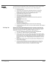
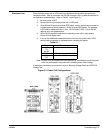
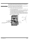
With the SCR device installed with the tightening bar and bolts (Figure 5-2), tighten the
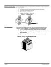
bolts as follows: (see Figure 5-3)
1. Tighten the nuts evenly until finger tight.
2. Tighten bolts in 1/4 turn increments.
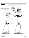
3. Use the SCR tightening pressure gauge and measure the deflection of the
Tightening bar. The middle and both ends of the gauge must be in solid contact
with the bar for an accurate reading. Correct pressure is indicated when the
gauge notch for the tightening kit number align.
Note: An anti-seize compound may be used on the bolt heads and threads to
reduce the torque required to obtain the correct mounting pressure.
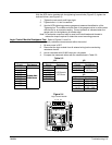
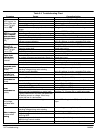
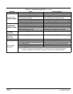
Logic Control Module Resistance Test Refer to Figures 5-1 and 5-4.
This test will verify resistance measurements within the control.
1. Be sure power is OFF.
2. Disconnect the logic module from all external wiring before conducting
resistance checks.
3. Use an ohmmeter with 20,000 ohms per volt greater.
4. Compare the measured values with the values shown in Table 5-2.
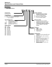
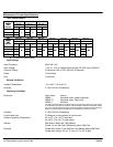
Table 5-2
MB MB
Line/Load Gates Control Power Input
Circuit Resistance Circuit Resistance Circuit Resistance
L1-L2 L1-GL1 14-15
130 to
L1-L3 L2-GL2 16-17
130 to
180 Ohms
L2-L3 L3-GL3
6.5 Ohms to
T1-T2
Greater than
T1-GT1
6
.
5 Ohms to
8.5 Ohms MA
T1-T3
G
reater
t
h
an
500k Ohms
T2-GT2 Control Power Input
T2-T3
500k Ohms
T3-GT3 Circuit Resistance
L1-T1 14-15 220 - 240
L2-T2 14-16 260 - 560
L3-T3 14-17 615 - 910
14-18 1150 - 1180
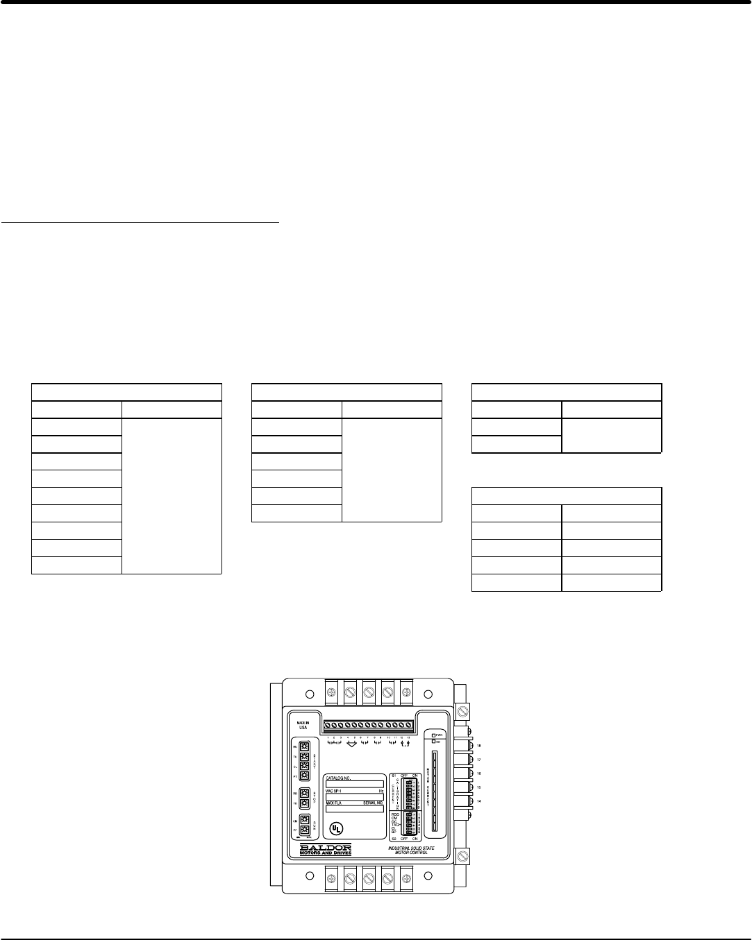
Figure 5-4
L1 L2 L3
T1 T2 T3
Logic Control Module