


Installation 2-3MN894
Installation
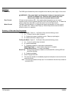
1. Mount the panel or enclosure to the mounting surface. The panel or enclosure must be
securely fastened to the mounting surface. Refer to the mounting dimensions in Section 6 of
this manual.
2. Ground the panel and control per NEC article 250 as well as state and local codes.
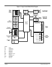
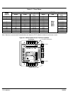
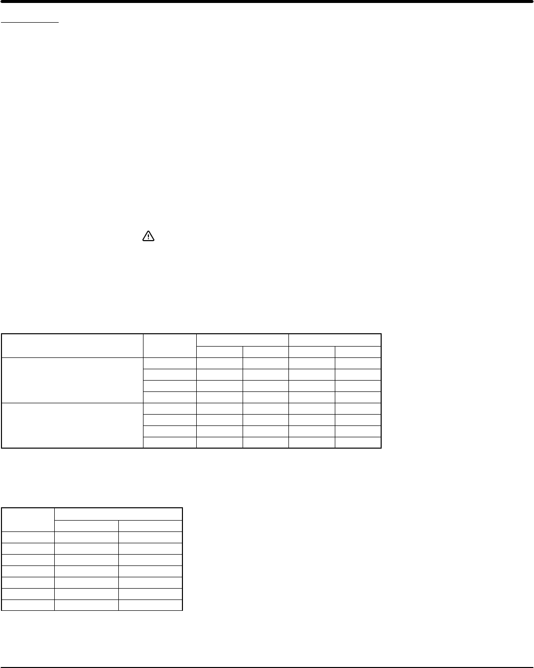
3. Use copper wire rated for at least 75°C. Refer to Figure 2-4 and Table 2-2 for wire size
recommendations.
4. Connect the incoming AC power wires from the power disconnect and/or protection devices to
L1, L2 and L3 terminals. Tighten each terminal as specified in Figure 2-4 and Table 2-2.
5. * Connect earth ground to the “GND” of the control. Be sure to comply with local codes.
6. Verify the input line voltage is correct.
7. For MA#−XX models, verify the line voltage selection jumpers on the LCM module are properly
set. For MB#−XX models, verify the control transformer primary taps are connected for the line
voltage applied.
8. Connect the three phase power leads of the AC motor to terminals T1, T2, and T3 of the Main
Circuit Terminals.
9. * Connect motor ground wire to the “GND” of the control. Be sure to comply with all applicable
codes.
Caution: Do not supply any power to the “Close To Run” terminals. Power
on these leads can damage the control. Use a dry contact type that
requires no external power to operate.
10. Connect the remaining control terminals as required for your installation. Refer to Figure 2-4 and
Table 2-2 for wire size and terminal torque specifications.
* Grounding by using conduit or panel connection is not adequate. A separate conductor of the
proper size must be used as a ground conductor.
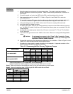
Table 2-2 Recommended Wire Size and Tightening Torque
Starter Rating
Terminal
Torque Wire Size
St
ar
t
er
R
a
ti
ng
Terminal
lb-in Nm AWG mm
2
A 20 2.5 10-16 6-1.5
8 16 and 30 AMPS
B 35 4 8 10
8
,
16
an
d 30 AMPS
C 12 1.4 12-22 4-0.34
D 45 5.1 6-14 16-2.5
A Note 1 Note 1 Note 2 Note 2
55 through 840 AMPS
B Note 1 Note 1 Note 2 Note 2
55
t
h
roug
h 8
4
0 AMPS
C 12 1.4 12-22 4-0.34
D 45 5.1 6-14 16-2.5
All wire sizes based on 75°C copper wire, 3% line impedance.
Higher temperature smaller gauge wire may be used per NEC and local codes.
Note1: Refer to the label on the equipment panel for line and load tightening torque values.
Note2: Line and Load wires sizes for 55 through 840 AMP models are as follows:
AMPS
Wire Size
AMPS
AWG mm
2
55 4 25
80 3 30
160 3/0 95
250 350 mcm 185
420 2x 300 mcm 2x 150
600 2x 500 mcm 2x 240
840 3x 500 mcm 2x 240