


Operation 3-3MN894
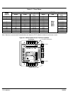
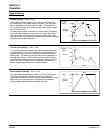
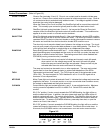
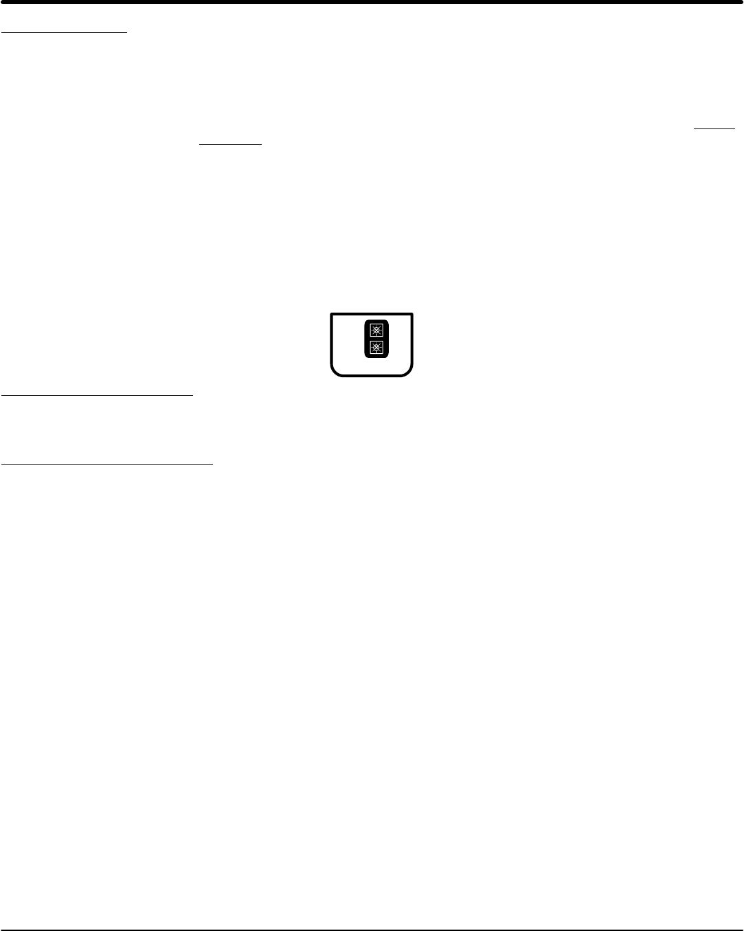
Run Adjustments (Refer to Figure 3-3).
Current Monitor Current monitor set point (CM) is adjustable from 50 to 400% FLA to monitor the running
current after the motor reaches the full run condition.
With CM enabled (S2-2=ON), if the running current exceeds the CM set point, the control
will shut down, the CUR MON contact will close, and the light will illuminate.
With CM disabled (S2-2=OFF), if motor current exceeds CM set point, the control will not
shut down, the CUR MON contact will close and the light will illuminate.
Power Factor Power factor effect (PF) is adjustable from 0 to 100%. PF is used to adjust the maximum
voltage applied to the motor under lightly loaded conditions to minimize motor current
with minimum motor load.
PF is enabled after the motor reaches full on condition.
PF should be turned off (CCW) if more than one motor is used with one control or if a
by-pass contactor is used.
Note: PF adjustment has no effect in bypass mode.
Figure 3-3
CM
PF
MIN MAX
R
U
N
Current Calibration Switch Refer to the multipurpose control Current Calibration Chart in Appendix A. Set switches
S1 to the motor FLA rating. Calibration is based on the motor nameplate full load
amperes (FLA), not necessarily actual running current. Motors with more than 6 times
locked rotor current may require a higher setting to start properly.
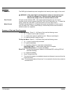
Operating Parameters Switch (Refer to Figure 3-4).
Switches S2-1 thru S2-6 select the operating modes that best fit the application.
S2-1 Ramp Down Disable (RDD).
In the “On” position: When the stop button is pressed, the control will immediately turn off.
User stop adjustments RD (ramp down time) and TD (ramp down initial starting torque)
are disabled.
In the “Off” position: When the stop button is pressed, the control will ramp down. In the
voltage mode of operation, ramp down time depends on RD and TD settings and the load
condition.
S2-2 Current Monitor (CM) “On” position: If the motor running current exceeds the Current Monitor (CM) setting, the
control will shut down. The shut down condition is indicated by the current monitor light
and the closure of the current monitor contact. The current monitor is typically used to
shut the control down when a jam occurs. To restart the control, press stop, then start; or
open the close to run circuit, then close it.
“Off” position: If motor running current exceeds the current monitor setting, the current
monitor light and contact will indicate this condition but the control will not shut down.
The current monitor can be used as an over and under current monitor.
S2-3 Over Current Indicator (OC).
“On” position: If an over current trip occurs (current exceeds 450% FLA), the control will
shut down and the condition will be indicated by the OC light and CM light and the
closure of the current monitor contact. To restart the control, press stop then start; or
open the close to run circuit, then close it.
“Off” position: An over current trip is indicated by the over current light and will not affect
the current monitor. The control will shut down.