


Operation 3-5MN894
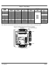
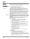
Control Connections (Refer to Figure 3-5).
CLOSE TO RUN Close to Run terminals 12 and 13. Close to run contact must be closed to initiate ramp
up and run. Close to Run contact must be opened to initiate ramp down to stop. Close to
run contact must be dry and electrically isolated contact. If a voltage is applied to these
terminals, the control may be damaged.
When the Close to Run circuit is closed, the Start/Run light will be on and the contact will
close. This normally open contact is typically used to seal in the start button circuit.
START/RUN Start/Run light and contact terminals 10 and 11. As long as the Closed to Run circuit
remains closed, the Start/Run light and contact will remain activated. This condition also
applies to an over current or a current monitor shutdown.
SHUNT TRIP Shunt Trip light and contact terminals 8 and 9. If the control detects a shorted SCR condition,
the shunt trip light will be on and the contact will close. The shunt trip contact is used to
operate a Shunt Trip device in the circuit breaker or similar disconnection means to remove
the motor and controller from the line should a shorted SCR condition occur.
The shunt trip circuit may also detect loss of phase or low voltage on a phase. The circuit
may not work properly on grounded delta systems or open delta systems. The Shunt Trip
circuit will trip when energized on single phase or an unbalanced line voltage.
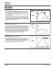
RAMP END Ramp End light and contact terminals 6 and 7. In the voltage or the tachometer modes,
when the starting ramp is completed and the control is in the full run mode, the ramp end
light will be on and the contact will close. The starting current limit is then disabled and
CUR MON (running current monitor) is enabled.
Note: Since most loads do not require full voltage and torque to reach full speed,
when control is in the voltage ramp mode, the motor will reach full speed
before the ramp end contact and light are activated. Ramp end will only be
activated after the motor and control reach full voltage.
The ramp end contact can be used to turn on other equipment. The ramp end contact
can be used to close the bypass contactor to reduce heat dissipation of the SCRs.
TACH Tachometer input terminals 4 and 5. The TACH input is used in the tachometer mode
(S2-4=ON). The input required for TACH feedback is a 0 to 10 volt DC signal with a
maximum 10 ms response time.
MTR PWR Motor Power light and contact at terminals 2 and 3. Indicates that voltage and current are
supplied to the motor. If a current monitor or an over current shut down condition occurs,
the contact is deactivated and the light is turned off.
CUR MON Current Monitor light and contact terminals 1 and 2. A user adjusted monitor. Maximum
running current is adjustable from 50% to 400% FLA. Switch S2-2 controls the CM
monitor.
S2-2 “On” position: If motor current exceeds the CUR MON setting, the light will be on
and the contact will close. In addition, the motor power and ramp end LEDs will be off
and their contacts will open. The control will shut down. The Start/Run light will stay on
and the contact will remain closed. Typically used to shut down the control in case of a
mechanical jam. To restart a CUR MON shutdown, press stop then start; or open the
close to run circuit, then close it.
S2-2 “Off” position: If current exceeds the CUR MON setting, the light will be on and the
contact will close for the duration of the over current. The control will not shut down. In
this mode, the CUR MON monitor can be used as an over and under current monitor.
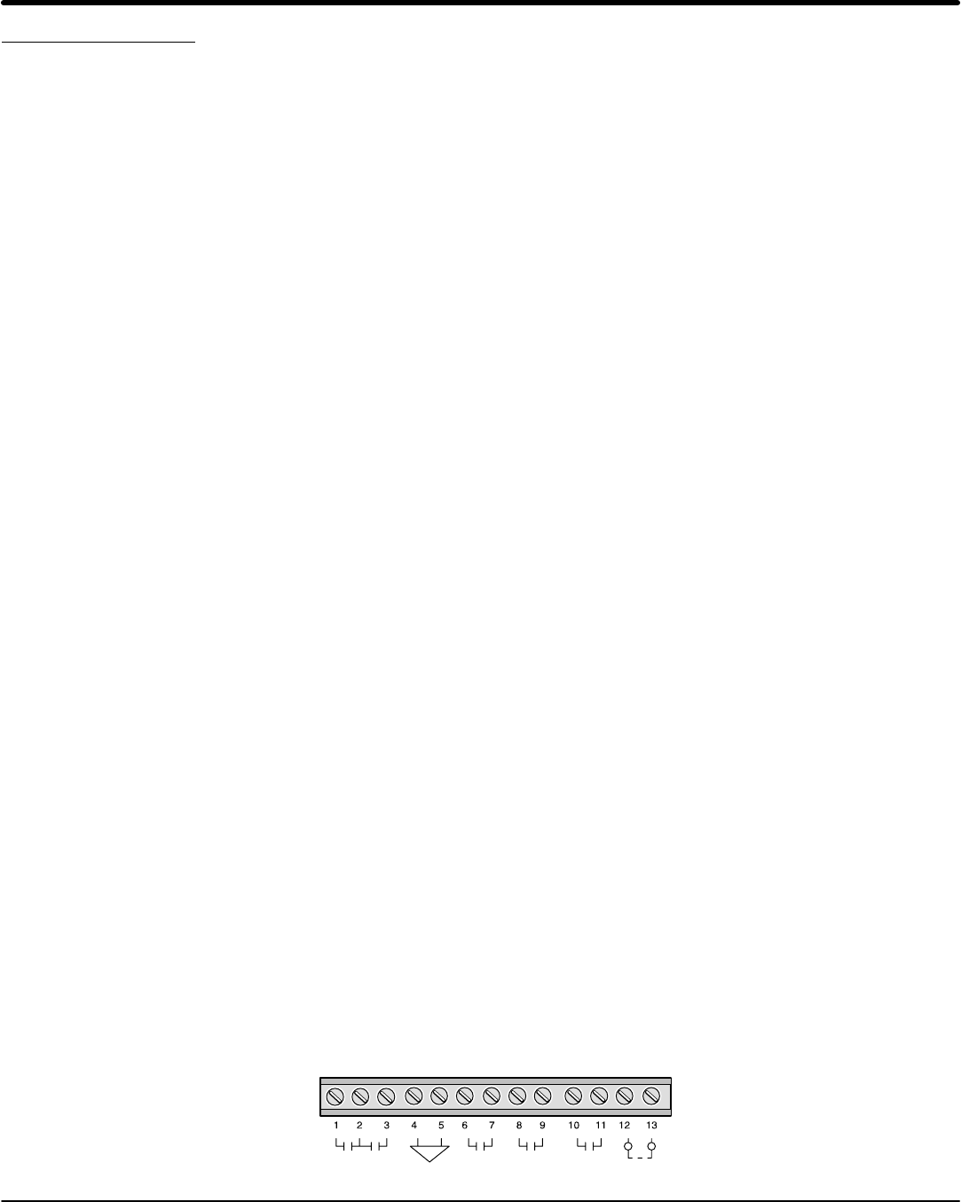
Figure 3-5
CLOSE
TO RUN
START
/ RUN
SHUNT
TRIP
Ramp
End
TachMTR
PWR
CUR
MON
+
−