


3-4 Operation MN894
S2-4 Tachometer and Voltage Ramp Select (TACH)
“On” position: The control is in the tachometer ramp mode during start and stop. Starting
and stopping times are independent of the load conditions. Ramp up (RU) is dependent
on the ramp up and current limit (CL) settings. RD is dependent on the RD and CL
settings.
Note: Current limit is disabled if S2-5 is “Off”. Operation in the tachometer mode
requires an isolated input tach signal of 0 to 10 volts DC with a 10 msec
response time or better. Tachometers with other voltage ranges may be used
with this control. Consult the factory for instructions.
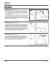
If the tachometer full speed voltage is less than 10 volts DC, the starting and stopping
times will be proportionally shorter. For example, if the starting and stopping times are
adjusted to 20 seconds with a 0 to 10 volt DC tachometer signal; for a 0 to 5 Volt DC
tachometer signal with the same setting, the time will be 10 seconds.
“Off” position: The control is operating in the voltage ramp mode during start and stop (if
ramp down is selected using S2-1). All user settings for start, stop and run can be used
to set up the control to meet the application requirements. Starting and stopping times
are dependent on the actual load condition and control settings.
S2-5 Current Limit Enable (CL)
“On” position: Starting and stopping current will not exceed the setting of the current limit
setting, except during PT, if pulse start is being used. Current limit must be set high
enough to allow the motor to start under maximum load conditions.
“Off” position: Current limit is disabled. Maximum motor current is then limited by the
over current shutdown circuit to 450% FLA, preset at the factory.
S2-6 By-Pass Select (BP) “On” position: When the end of ramp contact closes, the circuit breaker shunt trip circuit
(the Shunt Trip contact on the Multipurpose control module) is disabled after the starter is
in the full run condition. This allows the use of a by-pass contactor without tripping the
circuit breaker when the power cells are bypassed.
“Off” position: the Shunt Trip circuit is enabled at all times.
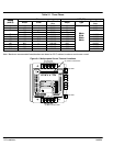
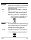
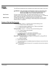
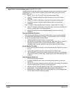
Figure 3-4
1
2
3
4
5
6
123456
O
N
OFF ONS2
RDD
CM
OC
TACH
CL
BP