


1-4 General Information MN894
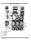
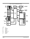
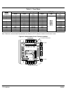
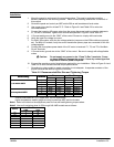
Major Components (Refer to Figures 1-1 and 1-2).
Logic Control Module (LCM)
The LCM (Logic Control Module) operates in the voltage ramp mode or current limit
mode during ramp up and ramp down (if ramp down is selected). The LCM controls the
amount of current that the power cells deliver to the motor during ramp up and ramp
down. It uses gates and synchronous timing circuits to control the firing times of the
SCR’s in the power cells. The current transformer provides the LCM with motor current
information. The on board current calibration switches (S1-1 thru S1-8), place burden
resistors in parallel with the current transformer to calibrate the LCM to the correct FLA
(full load amperes) of the motor being used.
Current Transformer (CT1) provides starting, stopping and running current information to the LCM. This
information is used to control starting and stopping current, current limit, current monitor
and over current shutdown, power factor effect and motor current bar graph indicator.
(CT2) is required only for sizes 160 through 840 amps. It steps down current to match
primary rating of CT1 transformer.
8, 16 and 30 amp models - CT1 is mounted inside the LCM housing.
55 and 80 amp models - CT1 is mounted externally on the panel.
160 to 840 amp models - CT1 and CT2 are mounted externally on the panel.
CT1 ratio is 6000:1
CT2 ratio is 500:5 for 160, 250 and 420 Amp models.
CT2 ratio is 1000:5 for 600 and 840 Amp models.
Power Cells (PC) Power cells control the voltage delivered to the motor during ramp up and ramp down (if
ramp down is enabled). The LCM controls the duty cycle of the SCR’s in the power cells
(“on” time versus “off” time of each SCR). A power cell contains two silicon controlled
rectifiers (SCR’s). The SCR’s are solid state switches that are able to control large
amounts of current with a small amount of gate current supplied by the LCM.
8, 16 and 30 amp models - six SCR’s are mounted inside the LCM housing.
55 and 80 amp models - SCR’s are mounted in an isolated package containing two
SCR’s for each power cell. With this type of package, three power cells are mounted to a
single heat sink at ground potential. A temperature switch is provided in each cell to
protect the power cell from overheating.
160 to 840 amp models - Each SCR is a disk type package containing one SCR. Two
SCR’s are clamped between two heat sinks. A temperature switch is provided to protect
the SCR assembly from overheating. Heat sinks are mounted on an insulated base with
a terminal block and snubber network. The snubber network is a capacitor resistor series
circuit wired in parallel with the disk type SCR’s. The snubber network enhances the
electrical characteristics of the SCR’s and provides transient voltage protection. This
arrangement makes up one power cell. The power cell is at line potential for both line
and load terminals when line voltage is applied.
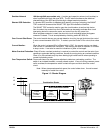
Protection Devices
Metal Oxide Varistors (MOV)
An MOV provides voltage surge protection. Voltage surges also called high voltage
spikes are caused by a number of sources. Short duration high voltage spikes caused by
starting and stopping other motor loads or switching On and Off capacitor banks may
appear on the incoming lines. Transients can occur from lightning storms or from other
lightly loaded devices on the same line, such as motors, transformers, or solenoids.
Electrical noise can be caused by lightning, arc welders and heat exchange equipment on
the same transformer bus line.
An MOVs provide protection by absorbing or clamping these transient energy levels.
High energy transients that exceed the MOV rating may damage the MOV and the
multipurpose starter.