


Section 1
General Information
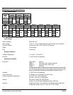
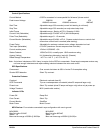
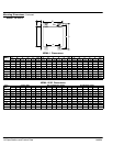
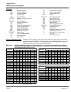
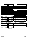
6-10 Specifications and Product Data MN894
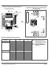
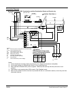
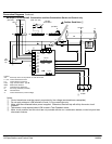
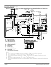
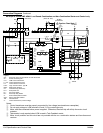
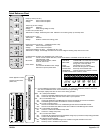
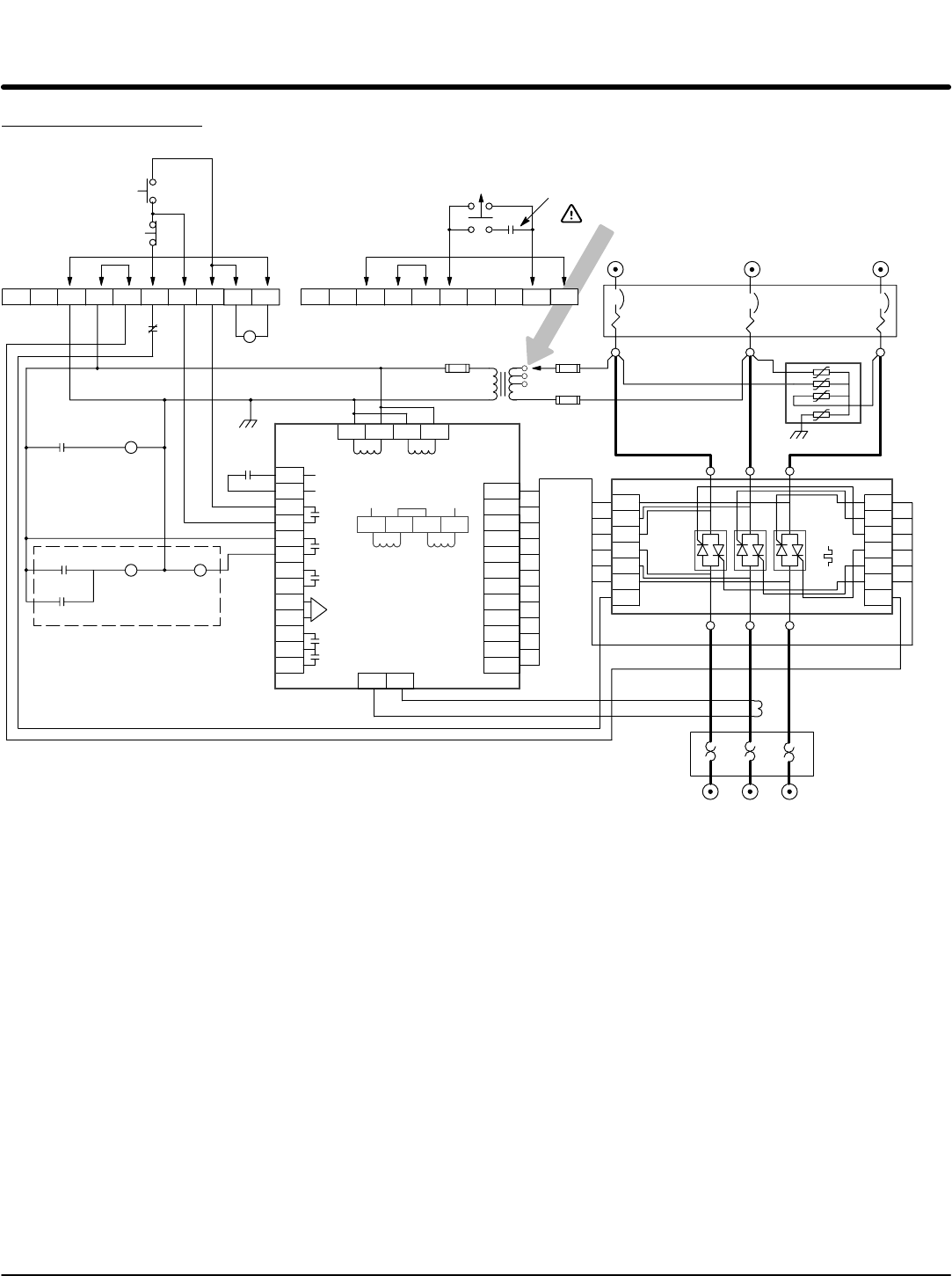
Connection Diagrams Continued
MB Style 55 and 80 AMP NEMA 1 and Panels Combination and Non-Combination Starter and Control only
13
12
11
10
9
8
7
6
5
4
3
2
1
16
17
14
15
L1
L2
L3
GL1
GL2
GL3
GT1
GT2
GT3
T1
T2
T3
19
20
Close
To Run
Start /
Run
Shunt
Trip
Ramp
End
Tach
Input
MTR
PWR
CUR
MON
CT Input
Shunt Trip
R2 CB
OL
R2
95
97 98
R1
12 8
95
R1
CF
X
115VAC
AB
F3
A
F1
A
F2
B
B
R1
13 14
9
10
7
8
64
5
31
2
OL
96
95
T1
T2
T3
L3
L2
L1
SA
GT3
GT2
GT1
GL3
GL2
GL1
SB
PC1
CT1
T1 T2 T3
To Motor
OL
CB
L1 L2 L3
Line Input
9
10
7
8
64
5
31
2
TB1TB1
Start
Stop
(Three Wire)
H
O
A
Two Wire
Control Device
(Hand - Off - Auto)
SCR SCR SCR
LCM
Legend:
CB - Shunt trip motor circuit protector or fuse disconnect.
CF - Power cell cooling fan.
CT1 - LCM current transformer.
F1, F2 - Control transformer fuses.
F3 - Control branch circuit fuse.
LCM - Logic control module - type M.
MOV - Metal oxide varistors.
OL - Overload relay (electronic).
PC1 - SCR power cell.
R1 - Run relay, DPDT.
R2 - Shunt trip relay, DPDT.
S - SCR overtemperature switch.
SCR - Silicon controlled rectifier.
TB1 - Terminal block.
X - Control transformer (control voltage).
S
13 14
MOV
Caution: Read Note
16
17
14
15
230VAC
Notes:
Control transformer must be properly connected for line voltage (see transformer nameplate).
Do not apply voltage to LCM terminals 12 and 13. Dry contact type only.
Motor must be connected before power is applied. Otherwise, the shunt trip will will trip the motor circuit
protector.
Tachometer is only required when LCM is used in Tach Feedback mode.
Motor circuit protector and this circuit are not provided with the non−combination starters and fuse disconnect
versions.