


C3 RS1100REV. A
9
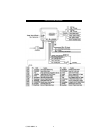
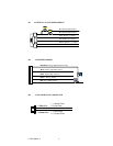
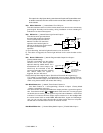
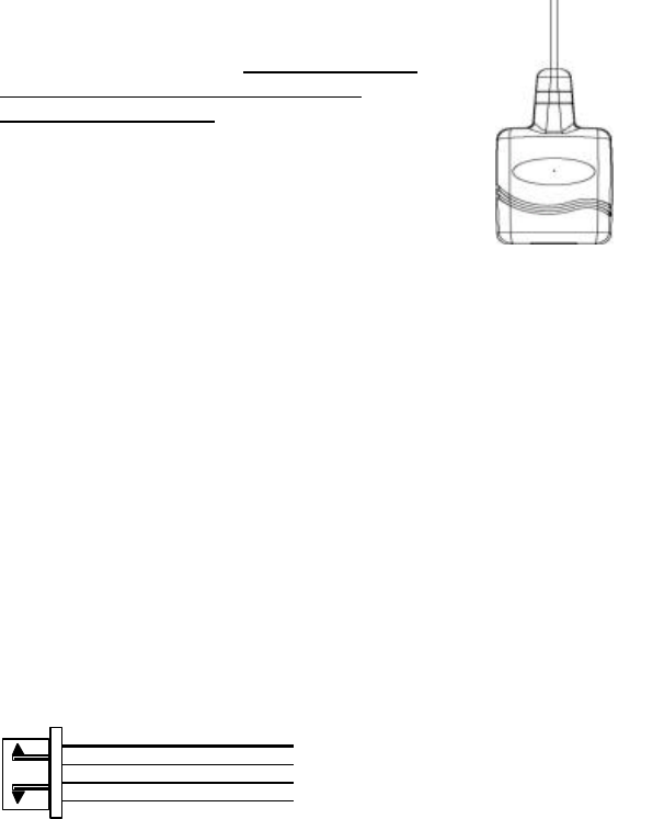
H7. 4-PIN BLACK CONNECTOR. – TWO-WAY TRANSCEIVER/ANTENNA
MODULE
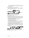
The Two-way transceiver/antenna mounting
location should be the upper left or lower left
corner of driver’s windshield. For optimum range
we suggest that the antenna be mounted
Antenna tip facing down.
Warning!
Do not mount in such a manner that it obstructs
the driver’s view.
- Remove the protective tape backing.
- Carefully align the two-way transceiver/antenna and apply to windshield.
- Route the black connector wire behind the trim and connect to the two-way
transceiver/antenna.
- Connect the other end to the control module.
- Special considerations must be made for windshield glass as some newer
vehicles utilize a metal-shielded window glass that will inhibit or restrict RF
reception. In these vehicles, route the two ways transceiver/antenna module
away from metallic s hielded window glass as far as possible.
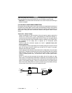
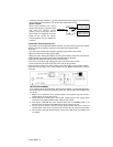
H8. 2 PIN BLUE CONNECTOR FOR THE VALET SWITCH:
Select a mounting location for the switch that is easily accessible to the driver of the
vehicle. The switch does not have to be concealed, however, concealing the switch
is always recommended, as this provides an even higher level of security to the
vehicle. Mount the valet switch in a hidden but accessible location. Route the valet
switch wires to the control module.
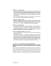
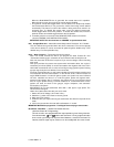
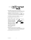
H9. 4 PIN ORANGE CONNECTOR 2 STAGE SHOCK SENSOR (ZONE 1 / 4)
1. Green Wire / Zone 1 Warn Away Input
2. Blue Wire / Zone 4 Ground Trigger
3. Black Wire / Ground
4. Red
Wire / +12Volts