


C3 RS1100REV. A
12
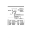
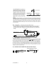
When the BLACK/WHITE wire is grounded, the remote start unit is operable.
When this wire is open from ground, the remote start is disabled.
1. The optional “remote start toggle switch” can be added on to temporarily disable
the Remote Start Device, it can prevent the vehicle from being remote started
accidentally. This feature is useful if the vehicle is being serviced or stored in an
enclosed area. To disable the remote start, move the optional remote start
enable toggle switch to the OFF position. To enable the remote start, move the
optional remote start enable toggle switch to the ON position.
2. If needed, this wire can connect to the PARK/NEUTRAL switch in the vehicle.
(See the TESTING YOUR INSTALLATION GUIDE)
IMPORTANT NOTE: This wire must have a “GROUND” to operate remote start.
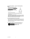
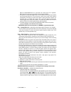
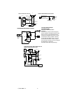
H6/9 Orange/White wire – 200mA Grounded Output when Disarmed - N.O. Disable
This wire will become grounded when the alarm is disarmed. The current capacity
of this wire is 200mA. It can be connected to optional Ignition disable relay / ECU
disable relay / Fuel Pump disable relay.
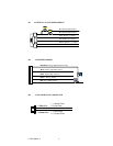
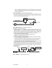
H6/10 White / Red wire – Tachometer Signal Connection –
Note: You should connect this wire if you program the Start Feature E – 2 to
“Tachometer checking type”, otherwise do not connect this wire and tap the end.
Note: No connection of this wire is required, if you use the voltage or timer checking
type mode.
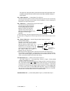
This input provides the remote start system with information about the engine’s
revolutions per minute (RPM). It can be connected to the negative side of the coil in
vehicle with conventional coils. In multi -coil and high energy ignition system locating
a proper signal may be more difficult. Once connected,
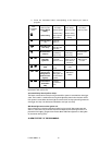
To test for a tachometer wire, a multi-meter capable of test AC voltage must be used.
The tachometer wire will show between 1V and 6V AC at idle, and will increase as
engine RPM increases. In multi-coil ignition system, the system can learn individual
coil wire. Individual coil wires in a multi-coil ignition system will register lower
amounts of AC voltage. Also, if necessary, the system can use a fuel injector control
wire for engine speed sensing. Common locations for a tachometer wire are the
ignition coil itself, the back of the gauges, engine computers, and automatic
transmission computers.
IMPORTANT! Do not test tachometer wires with a test light or logic probe. The
vehicle will be damaged.
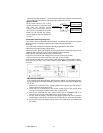
How to find a tachometer wire with your multi -meter
1. Set the ACV or AC voltage (12V or 20V is fine.)
2. Attach the (-) probe of the meter to chassis ground.
3. Start and run the vehicle.
4. Probe the wire you suspect of being the tachometer wire with the red probe of the
meter.
5. If this is the correct wire the meter will read between 1V and 6V.
IMPORTANT NOTE: M ust program the “Tach Signal” before trying to remote start.
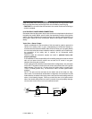
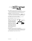
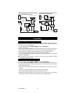
H6/11 Black / Violet Wire– (-) 200mA Timer Control Channel 6
(See Alarm Feature C – 7 Programming)
This wire is built-in user-programmable timer output provides a ground through this wire.
Press the transmitter and buttons at the same time. You may program the built-in
timer to send a ground signal for any time interval between 1 second and 2 minutes. For
instance, this timer output may be used to turn on the headlight with the remote control.