


C3 RS1100REV. A
7
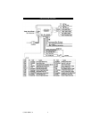
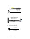
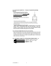
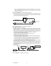
Red Wire (2) — +12V Power Input
Remove the two 20A fuses prior to connecting these wires and do not replace them
until the satellite has been plugged into the control module. These wires are the
source of current for all the circuits the relay satellite will energize. They must be
connected to a high current source. Since the factory supplies (+) 12V to the key
switch that is used to operate the motor, it is recommended that these wires be
connected there.
Note: If the factory supplies two separate (+) 12V feeds to the ignition switch,
connect one RED wire of the satellite to each feed at the switch.
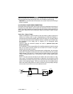
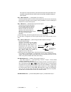
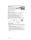
Yellow Wire – Ignition 1 Output
Connect the YELLOW wire to the ignition 1 wire from the ignition switch. The
ignition wire should receive “12 volts” when the ignition key is in the “ON” or “RUN”
and “START” or “CRANK” position. When the ignition is turned “OFF”, the ignition
wire should receive “0” voltage. The YELLOW wire must be connected.
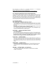
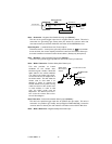
PINK Wire – Ignition 2 Output
Some vehicles have [2] ignition wires that must be power. Connect the PINK wire
to the ignition 2 wire from the ignition switch. The ignition wire should receive “12
volts” when the ignition key is in the “ON” or “RUN” and “START” or “CRANK”
position. When the ignition is turned “OFF”, the ignition wire should receive “0”
voltage. If the PINK wire is not used, cap the end of the wire.
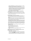
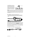
Brown Wire –Accessory Output (Heater /AC Output)
Connect the BROWN wire to the accessory wire in the vehicle that powers the
climate control system.
An accessory wire will show + 12 volts when the ignition switch is turned to the
“ACCESSORY” or “ON” and “RUN” positions, and will show 0 Volts when the key
is turned to the “OFF” and “START” or “CRANK” position. There will often be more
than one accessory wire in the ignition harness. The correct accessory wire will
provide power to the vehicle’s climate control system. Some vehicles may have
separate wires for the blower motor and the air conditioning compressor. In such
cases, it will be necessary to add a relay to power the second accessory wire.
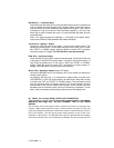
H2 RS232 C3 Two way SERIAL DATA PORT CONNECTION:
This connector is to be used for Serial Data communications with idatalink
modules by Auto Page only! DO NOT CONNECT THIS TO ANY OTHER
WIRING!
This connector will transmit digital codes to operate all functions of Autopage data
modules. When these modules are used, no other data bus connections need to be
made to the RS-900. The Data Bus module will receive its commands directly from the
CPU of the RS-900. This will provide greater theft protection as well as aid in the
installation of this product. The RS-232 serial harness is provided with all Autopage
serial data modules and is not included with the RS-900. This two-way data port has