


C3 RS1100REV. A
17
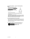
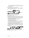
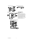
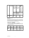
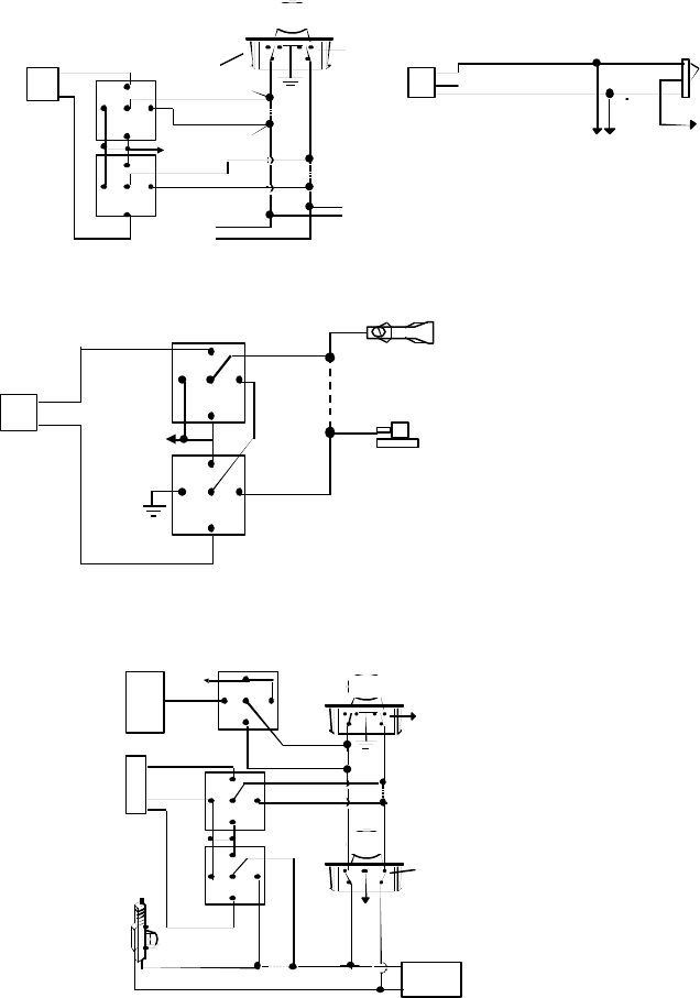
VACUUM OPERATED CENTRAL LOCKING
Green Wire
Blue Wire
+12V
X
Cut
Compressor
Door Switch
30
86
87a
85
87
30
86
87a
85
87
3 Pin
Plug To
Alarm
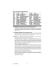
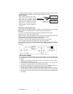
VACUUM OPERATED DOOR
LOCKING SYSTEM:
TYPICAL OF MERCEDES BENZ
AND AUDI.
Locate the wire under the driver's kick panel.
Use the voltmeter connecting to ground, verify
that you have the correct wire with the doors
unlocked, the voltmeter will receive "12 volts".
Lock the doors and the voltmeter will read
"0 volt". Move the alligator clip to +12V and
the voltmeter will receive "12 volts". Cut this
wire and make connections. Be sure to program
door lock timer to 3.5 seconds.
(See Alarn Feature B – 3 Programming.)
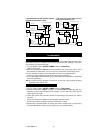
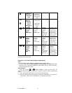
+12V
Master Door
Lock Switch
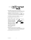
X
X
Splice
Splice
Cut the Existing
Lock Wire
To Door
Lock
Motor
To Slave Door
Lock switches
Cut the Existing
Unlock Wire
3 Pin Plug
To Alarm
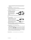
5-WIRE ALTERNATING DOOR LOCK
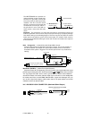
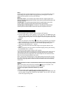
30
86
87a
85
87
30
86
87a
85
87
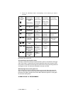
Red +12V
Green Wire
Blue Wire
POSITIVE TRIGGER DOOR LOCK SYSTEM
Blue Wire Door lock
Green Wire Door Unlock
Locking
Master
Switch
To Exiting
Door Lock Relay
+ 12V
Red (not used)
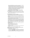
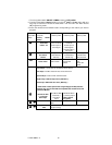
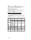
2 STEP DOOR UNLOCK WIRE CONNECTION FOR
5 WIRE ALTERNATING DOOR LOCKS
+12V
Cut the Existing
Lock Wire
Cut Existing Unlock
X
Cut the Unlock Wire
Lock
Unlock
OEM Door Master Lock
Switch
OEM Slave
Door Lock
Switch
+12V
Lock
Unlock
To All Other
Door Lock
Motors
H10/12
:
20-Pin
Plug
From
Alarm
Pink Wire
x
X
Blue Wire
OEM Driver’s
Door Lock Motor
+ 12V
85
86
87
87a
30
30
87
85
87a
86
30
87
85
87a
86
Green Wire
H7
:
3 Pin
Plug
To
Alarm
Red +12V