


C3 RS1100REV. A
6
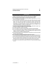
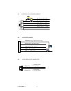
WIRING
Keep wiring away from moving engine parts, exhaust pipes and high-tension cable.
Be sure to tape wires that pass through holes on the firewall to prevent fraying.
CAUTION: Do not connect the wire harness to the control module until all wiring to
vehicle is complete .
H1: 6 PIN HEAVY GAUGE WIRING CONNECTIONS:
Remember that what the system does to start a vehicle is to duplicate the functions of
the ignition key switch! Below, we will explain the three basic functions of the ignition
switch. Since this installation will require analysis of the ignition switch functions, we
recommend making the three connections below at the ignition switch harness
directly.
Violet Wire —Starter Output
Careful consideration for the connection of this wire must be made to prevent the
vehicle from starting while in gear. Understanding the difference between a
mechanical and an electrical Neutral Start Switch will allow you to properly identify
the circuit and select the correct installation method. In addition you will realize why
the connection of the safety wire is required for all mechanical switch
configurations.
Failure to make this connection properly can result in persona l injury and
property damage.
In all installations it is the responsibility of the installing technician to test the remote
start unit and assure that the vehicle can not start via RF control in any gear
selection other than park or neutral.
In both mechanical and electrical neutral start switch configurations, the connection
of the VIOLET wire will be made to the low current start solenoid wire of the ignition
switch harness. This wire has +12 volts when the ignition switch is turned to the
“START” (CRANK) position only. This wire has 0 volts in all other ignition switch
positions.
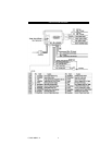
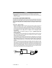
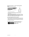
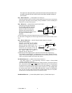
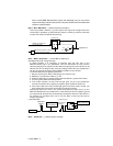
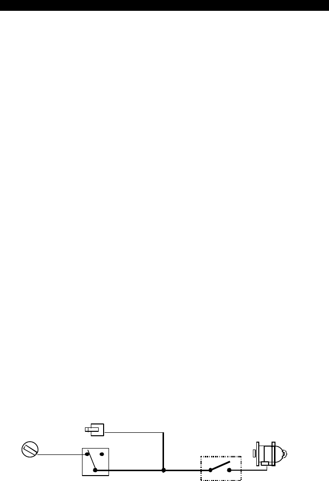
NOTE: This wire must be connected to the vehicle side of the starter cut relay
(when used). For the electrical neutral switch configuration, this connection must be
made between the starter inhibit relay (when used) and the neutral safety switch as
shown in the following diagram. Failure to connect this wire to the ignition switch
side of the neutral safety switch can result in personal injury and property damage.
SEE NEUTRAL START SAFETY TEST FOR FURTHER DETAILS.
Start Cut Relay
(When Used)
VIOLET
Wire
Closed in Park or
Neutral Only
Ignition
Switch
“Start”
“On”
Neutral Safety
Switch
“
Acc”
“Off”
Starter