


C3 RS1100REV. A
31
3. NEUTRAL START SAFETY TEST:
1. Set the vehicle parking brake.
2. Block the drive wheels to prevent vehicle movement.
3. Sitting in the vehicle, turn the ignition switch to “ON” or “RUN” position. But do not
start the engine.
4. Step on the brake pedal and shift the gear selector into “DRIVE” (D).
5. Put your foot over the brake pedal but do not press down on it. Be ready to step
on the brake to shut down the Remote Start Device.
6. Start the vehicle using remote transmitter.
a.If the starter does not engage, the test is complete.
b.If the starter engages, immediately step on the brake pedal to shut down the
system, recheck your VIOLET wire (H1/1 starter output wire) connection. The
heavy gauge VIOLET wire must be connected to the ignition switch side of the
Neutral Start Switch. If the vehicle you are working on does not have an
Electrical Neutral Safety Switch, it will be necessary to reconfigure the Remote
Starts Wiring to accommodate this vehicle. The information concerning the
Mechanical Neutral Safety Switch provided below will help you to determine if
the vehicle you are working on has this type of safety switch and will provide
alternative wiring methods to accommodate this situation.
MECHANICAL NEUTRAL SAFETY SWITCH CONSIDERATIONS:
Mechanical neutral safety switch configurations differ slightly in that they do not offer
the same level of safety when installing a remote start device. Often when the ignition
switch is turned off while the gear selector is in any position other than park or neutral,
the mechanical function will not allow the key to be turned to the start position or be
removed from the ignition cylinder. This configuration prevents mechanical operation
while the vehicle is in gear but offers no consideration for electrical operation. Because
of this potential problem, this installation requires the additional connection of a safety
wire from the remote start device to the vehicle PARK/NEUTRAL ECM input or the
vehicle key in sensor. This connection will prevent remote start operation if the key is
left in the ignition switch regardless of the gear selector position.
PARK/NEUTRAL ECM INPUT:
The Park/Neutral ECM input is the preferred method of installation. This not only
maintains the integrity of the factory circuit, it is also the easiest to install, providing the
vehicle you are working on has this ECM input.
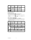
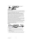
The installation required for this application (shown below), indicates in the slight
reconfiguration of the control switch wiring. Shown is a typical GM Park/Neutral ECM
input circuit. To connect the Remote Start unit to the GM Park/Neutral ECM input:
1. Locate the Orange/Black reference wire in the “C2” connector found at the ECM in
GM B Body vehicles or, locate the equivalent reference wire in the vehicle you are
installing the Remote Start Unit in.
2. Connect the BLACK/WHITE Neutral Safety Switch wire (H6/8) to this reference
wire.
NOTE: If the optional remote starts enable toggle switch is installed, connect the one
side the enable switch to this reference wire and connect the other side of the enable
switch to the BLACK/WHITE Neutral Safety Switch wire (H6/8) of the Remote Start unit.
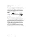
The reference diagram on the next page shows a typical GM B Body ECM reference
wire and how it is to be connected to the Remote Start Unit.