


C3 RS1100REV. A
32
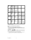
Ignition
P
1
2
D
N
R
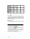
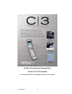
Electronic Control Module (ECM)
Solid State, Do Not Measure
Resistance
To Neutral Safety
Switch Input wire
Black/White (H10/1)
Optional Enable Switch
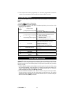
KEY IN SENSOR CIRCUITS:
If the vehicle you are working on does not have or you cannot locate the ECM reference
wire, there are two alternatives available. Although not preferred, the vehicle Key In
Sensor may be reconfigured to allow a margin of safety and will prevent the vehicle
with a Mechanical Neutral Start Switch from starting in gear.
WE ADVISES THAT YOU MAINTAIN THE FACTORY CIRCUIT WHENEVER POSSIBLE.
The following two circuits may be used only if the above circuit is not available.
NOTE: When completing an installation using either of the following key in sensor
circuits, if the operator inserts the ignition key while the vehicle is running under the
control of the Remote Start, the vehicle will shut down. This must be explained to the
operator as it is in contrast to the normal operation of a vehicle utilizing an electrical
neutral start switch and is inconsistent with the operators manual.
Additional information concerning Key in Sensor methods 1&2 are listed below and
should be reviewed before considering either alternative.
Method 1 will allow the safety required for the remote start unit and prevent the vehicle
from starting while in any gear other than Park or Neutral while the key is in the ignition
cylinder howeve r, if the key is left in the ignition switch and the door is left opened, the
added relay will be energized causing a 150mA drain on the battery.
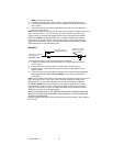
Method 2 will allow the safety required for the remote start unit and prevent the vehicle
from starting while in any gear other than Park or Neutral while the key is in the ignition
cylinder. However, the original factory key in chime module will not alert the owner that
the key has been left in the ignition switch. In addition, this may also affect other
warning tones such as the light on reminder.
These situations should be carefully considered before altering the vehicle’s wiring
and must be fully explained to the consumer.
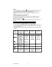
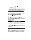
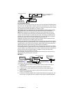
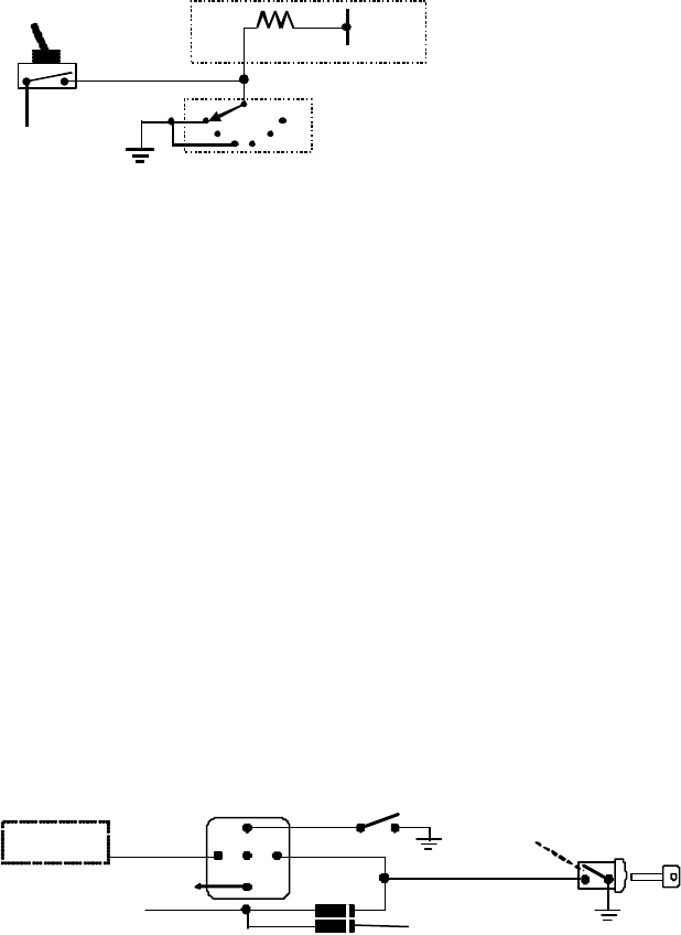
METHOD 1
+ 12 V
Ignition Key In Sensor
Switch Closes with Key
In Ignition Cylinder
Switch
Drivers Door Pin Switch
87a
86
30
87
85
Key In
Chime Module
Connected to (-
) Negative
Safety Input Wire
White/ Black (H6/20)
To Hood Pin Switch
Safety Shut Down (H6/8)
1N4003
+
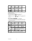
To connect to the key in sensor as shown in method 1:
A. Locate the control wire that connects the driver’s door pin switch to the key in
sensor switch.
B. Cut this wire and connect the ignition cylinder side to chassis ground.
C. Locate the key in sensor switch wire that connects the chime module to the
ignition cylinder.
D. Cut this wire and connect the ignition cylinder side to terminal 30 of a P&B
VF45F11 or equivalent relay.
E. Connect the cathode (striped) side of a 4003 series diode to this same wire, and
connect the (non striped) side to the negative safely input wire (WHITE/ BLACK)