2-13
SPEC
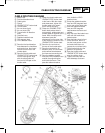
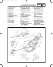
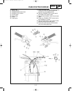
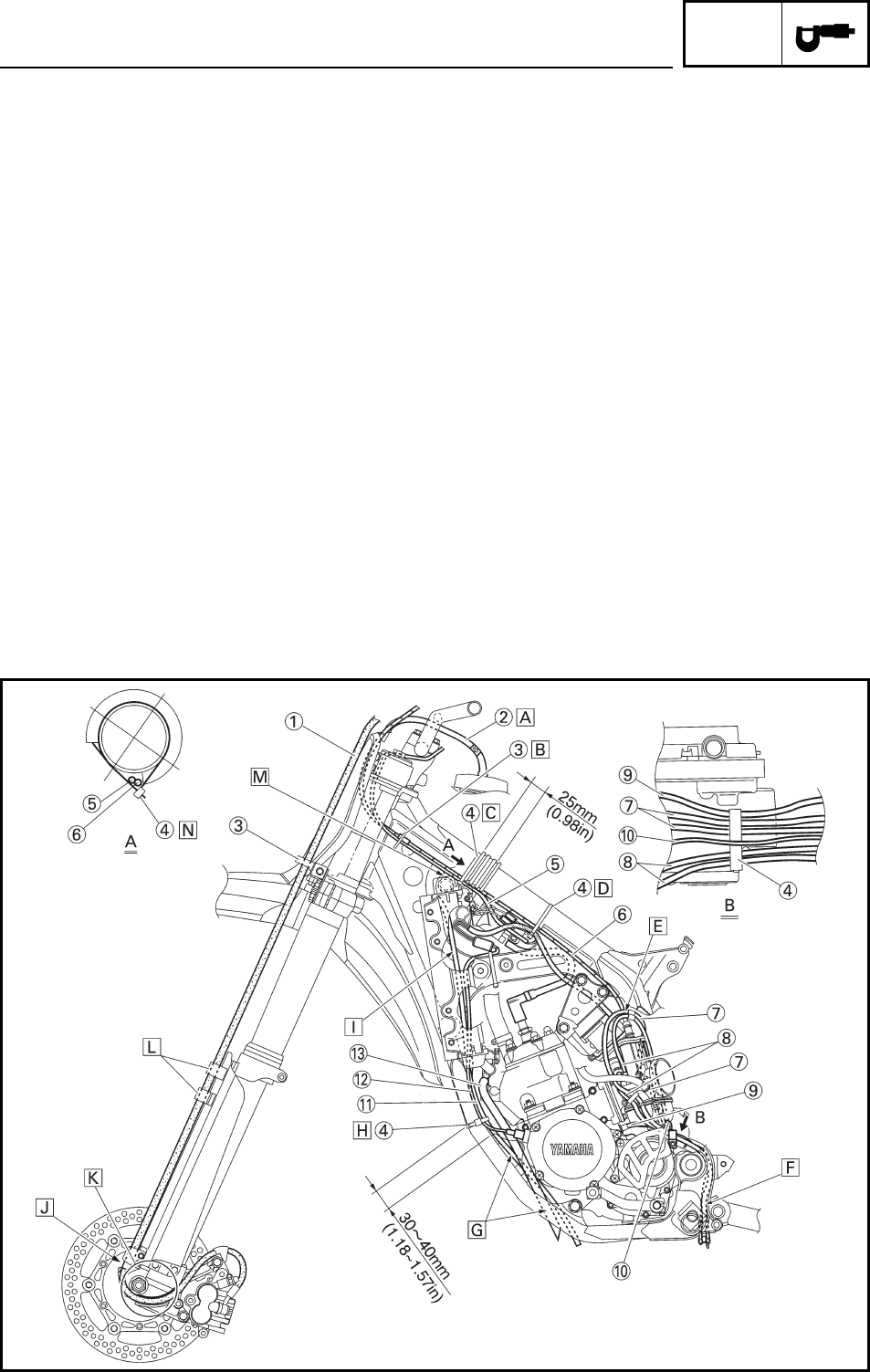
CABLE ROUTING DIAGRAM
EC240000
CABLE ROUTING DIAGRAM
1 Brake hose
2 Fuel tank breather hose
3 Cable guide
4 Clamp
5 “ENGINE STOP” button lead
6 Throttle cable
7 Air vent hose (right)
8 Air vent hose (left)
9 Transmission oil breather
hose
0 Overflow hose
q Radiator breather hose
w CDI magneto lead
e YPVS breather hose
A Pass the fuel tank breather
hose between the handlebar
and tension bar, then insert
its end into the hole of the
number plate.
B Pass the throttle cable and
“ENGINE STOP” button lead
into the cable guide. Align
with the cable guide the
front end of the tape on the
throttle cable.
C Clamp the throttle cable and
“ENGINE STOP” button lead
to the frame. With the clamp
ends downward, tighten the
throttle cable to the extent
that it moves smoothly.
D Clamp the “ENGINE STOP”
button lead (where there is
no protector), wireharness and
throttle cable all together to the
frame. With the clamp ends
downward, pass the
wireharness on the outer side
of the chassis in relation to the
“ENGINE STOP” button lead.
E Pass the air vent hose at
the rear of the throttle cable.
F Pass the transmission oil
breather hose, air vent hoses
and overflow hose between
the frame and connecting rod.
G Pass the radiator breather
hose and YPVS breather hose
outside the engine bracket
and inside the frame. Then
pass the radiator breather
hose inside the YPVS
breather hose.
H Clamp the radiater breather
hose and CDI magneto lead
on the rear of the down-tube.
I Pass the radiater breather
hose and CDI magneto
lead between the frame and
radiator.
J Align the top of the brake hose
neck with the brake hose
holder bottom.
K Pass the brake hose in front
of the axle boss, then fit it
into the hose groove so that
the brake hose does not
contact the nut (wheel axle).
L Fit the brake hose into the
guide on the protector.
M Pass the throttle cable and
“ENGINE STOP” button lead
over the radiator hose.
N Tighten the clamp with its
ends sideways as shown.
5MV-9-10-2 6/12/00 7:24 PM Page 2-13


