


Unit 6: Maintenance
Lt408 Operator Manual
6-4 PN: 9001152A
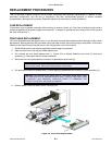
ROLLER REPLACEMENT
The printer’s three rubber rollers are considered to be high-wear components due to constant treading of the print
media and ribbon stock against their contact surfaces. This constant contact will eventually wear grooves into the
rubber material and negatively effect print output.
The procedure below applies for all three rubber rollers. However, some rollers do not incorporate the use of
spacer (5) so in those cases, that process is to be ignored.
1. Switch off the printer and observe appropriate lockout-tagout procedures.
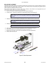
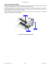
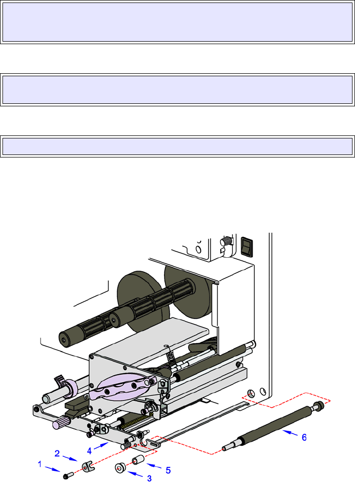
2. Loosen screw (1, Figure 6-3) sufficiently to rotate bearing clamp (2) from bearing (3).
3. Withdraw bearing (3) from chassis (4) and spacer (5) from defective roller (6) consecutively.
4. Withdraw defective roller (6) from chassis (4) and insert replacement roller (6) in its place.
5. Insert spacer (5) onto the free end of replacement roller (6) followed by bearing (3).
6. Rotate bearing clamp (2) onto bearing (3) and secure using screw (1).
7. Repeat steps 2 through 6 for all other roller assemblies that require replacement.
8. Restore power and test print.
Figure 6-3, Roller Replacement
NOTE: Figure 6-** shows screw (1) and bearing clamp (2) as being removed for
display purposes only. It is not necessary to remove those components for roller
replacment.
NOTE: Ignore removal of spacer (5) if that component is not present on the roller
being replaced.
NOTE: To remove the roller, move it toward its free end and then lift upward.