


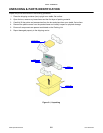
Unit 3: Installation
Lt408 Operator Manual
3-10 PN: 9001152A
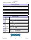
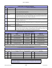
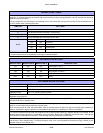
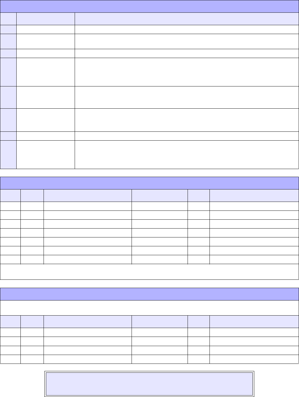
READY/BUSY INTERFACE SIGNALS
PIN DIRECTION SIGNAL DEFINITION
1 Reference FG (Frame Ground)
2 To Host TD (Transmit Data) - Data from the printer to the host computer. Sends X-On/X-Off characters
or status data (bi-directional protocols).
3 To Printer RD (Receive Data) - Data to the printer from the host computer.
4 To Host RTS (Request to Send) - Used with Ready/Busy flow control to indicate an error condition.
RTS is high and remains high unless the print head is open (in this case, RTS would return to
the high state after the print head is closed and the printer is placed back on-line) or an error
condition occurs during printing (e.g., ribbon out, label out).
5 To Printer CTS (Clear to Send) - When this line is high, the printer assumes that data is ready to be
transmitted. The printer will not receive data when this line is low. If this line is not being used,
it should be tied high (to pin 4).
6 To Printer DSR (Data Set Ready) - When this line is high, the printer will be ready to receive data. This
line must be high before data is transmitted. If this line is not being used, it should be tied high
(to pin 20).
7 Reference SG (Signal Ground)
20 To Host DTR (Data Terminally Ready) - This signal applies to Ready/Busy flow control. The printer is
ready to receive data when this pin is high. It goes low when the printer is off-line, either
manually or due to an error condition, and while printing in the single job buffer mode. It will
also go low when the data in the buffer reaches the buffer near full level.
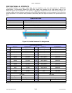
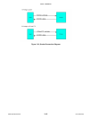
READY/BUSY CABLE REQUIREMENTS
DB9 DB25 HOST DIRECTION DB25 PRINTER
1 1 FG (Frame Ground) Bi-Directional 1 FG (Frame Ground)
2 3 RD (Receive Data) To Host 2 TD (Transmit Data)
3 2 TD (Transmit Data) To Printer 3 RD (Receive Data)
8 5 CTS (Clear To Send) To Printer DB9-6 4 RTS (Request To Send)
4 20 DTR (Data Terminal Ready) To Printer DB9-4 5 DSR (Data Set Ready)
6 6 DSR* (Data Set Ready) To Host 6 DTR (Data Terminal Ready)
5 7 SG (Signal Ground) Bi-Directional 7 SG (Signal Ground)
* This connection at the host side of the interface would depend upon the pin that is being used as the Ready/Busy signal by
the driving software. Typically, on a PC, it would be either CTS (pin5) or DSR (pin 6) on a DB-25 connector.
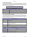
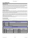
X-ON/X-OFF CABLE REQUIREMENTS
Communicates with the host to determine if the printer is ready to receive data by sending “XON” (HEX 11H) or “XOFF” (HEX
13H) code to the TD line. The single and multiple item buffers are switchable in the Interface Mode of the printer.
DB9 DB25 HOST DIRECTION DB25 PRINTER
1 1 FG (Frame Ground) Bi-Directional 1 FG (Frame Ground)
2 3 RD (Receive Data) To Host 2 TD (Transmit Data)
3 2 TD (Transmit Data) To Printer 3 RD (Receive Data)
5 7 SG (Signal Ground) Bi-Directional 7 SG (Signal Ground)
NOTE: Depending on the host used, it may be required to loop CS and RS
(maintaining at high-level) on the host side. For more information, refer to the host
computer documentation.