


Unit 3: Installation
Lt408 Operator Manual
3-16 PN: 9001152A
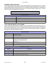
ALL INTERFACES
RECEIVE BUFFER
The data stream is received from the host to the printer one job at a time. This allows the software program to
maintain control of the job print queue so that it can move a high priority job in front of ones of lesser importance.
A multiple job buffer allows the printer to continuously receive print jobs while compiling and printing other jobs at
the same time. It acts much like a Print buffer to maximize the performance of the host and the printer.
The printer receives and prints one job at a time. If a print job exceeds the buffer size, transmission will be rejected
by the printer. Flow control protocols to throttle transmission are not used. Error conditions that occur during the
Print Data transmission will cause the printer to return a NAK.
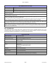
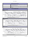
ACK/NAK PROTOCOL
Bi-Directional ACK/NAK protocol is used for error control. In a normal transmission sequence when the
transmission is received, the printer will return an ACK (06H) signifying that it was received without a transmission
error. After the transmission command structure has been analyzed, a status byte is returned to the host. This
status byte informs the host of the validity of the command structure.
If the command structure is error free, the printer proceeds with the print operation. When the print operation is
completed, a Printer Status message is returned to the host. If an error was detected during the initial transmission
sequence, a NAK (15H) will be returned signalling to the host that the received transmission contained errors and
must be resent. If the returned Status byte indicates a command structure error, the error must then be corrected
before the print data is resent to the printer.
A valid transmission to the printer must be bounded by an STX/ETX pair, with the STX (02H) signifying the start of
the Print Data and ending with an ETX (03H) signifying the end.
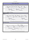
STATUS5 RETURN
This communication protocol is designed for the purpose of monitoring and controlling print data status in the host
and featuring various functions.
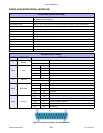
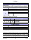
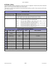
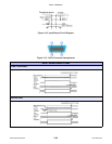
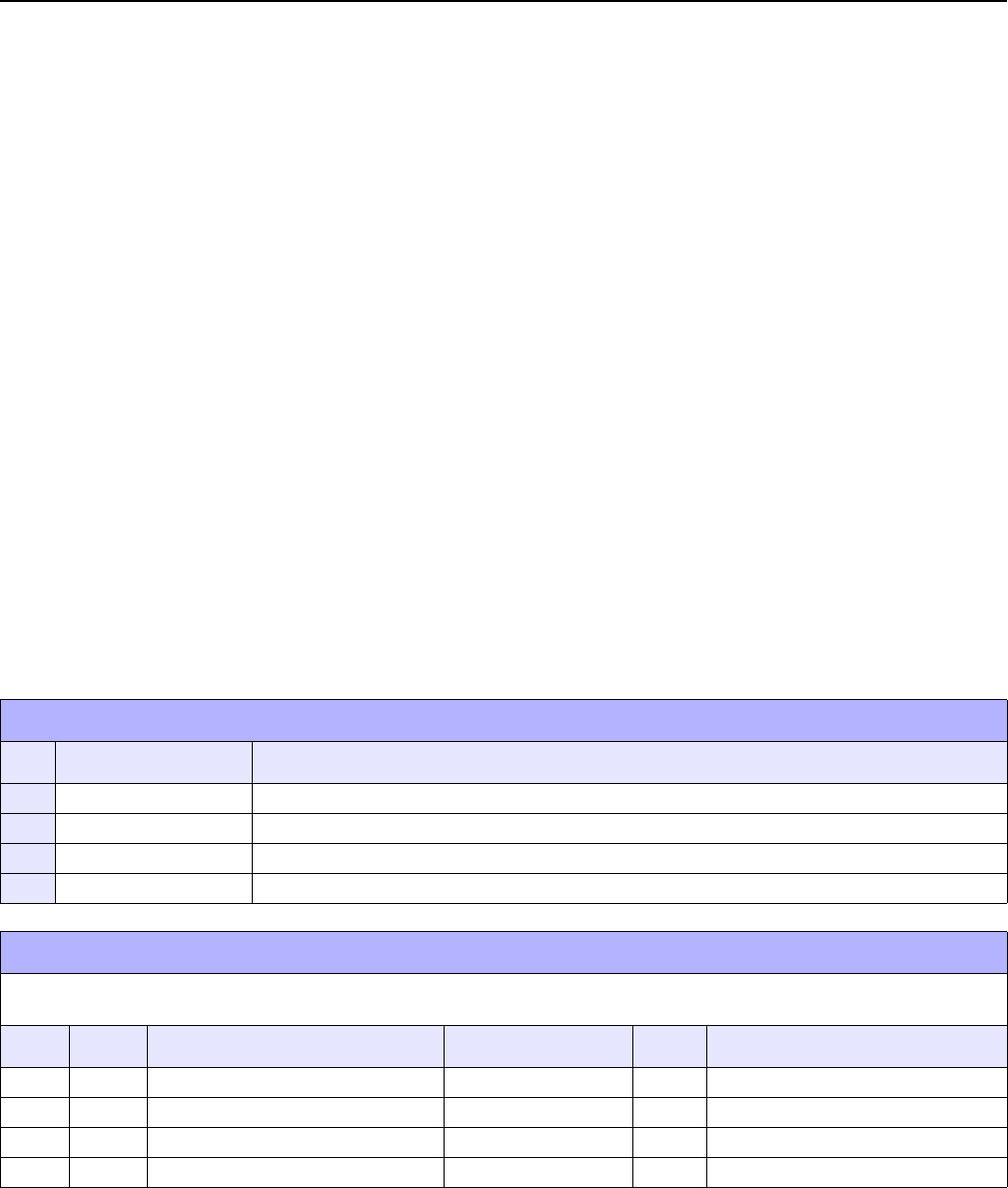
INTERFACE SIGNALS
PIN DIRECTION SIGNAL DEFINITION
1 Reference FG (Frame Ground)
2 To Host TD (Transmit Data) - Data from the printer to the host computer.
3 To Printer RD (Receive Data) - Data to the printer from the host computer.
7 Reference SG (Signal Ground)
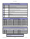
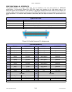
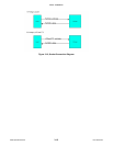
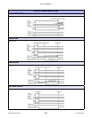
CABLE REQUIREMENTS
Depending on the host used, it may need to loop CS and RS (maintaining at high level) on the hose side. For additional
information, refer to the host computer documentation.
DB9 DB25 HOST DIRECTION DB25 PRINTER
1 1 FG (Frame Ground) Bi-Directional 1 FG (Frame Ground)
2 3 RD (Receive Data) To Host 2 TD (Transmit Data)
3 2 TD (Transmit Data) To Printer 3 RD (Receive Data)
5 7 SG (Signal Ground) Bi-Directional 7 SG (Signal Ground)