


8
S4359146
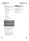
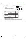
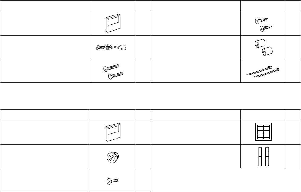
Table 1-8 (Accessories for the Weekly Timer)
Part Name Figure
Q’ty
Part Name Figure
Q’ty
Weekly timer 1 Wood screws 2
1 Spacers 2
2 Clampers 2
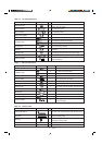
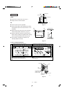
Table 1-9 (Accessories for the System Controller)
Part Name Figure
Q’ty
Part Name Figure
Q’ty
System controller 1 1
41
Machine screws
M4 × 1 in.
Connecting wiring
length 4 ft.
Rubber bushing
(7/8 in.)
Label
(Identification label)
2
Screws for fixture
(1-3/16 in.)
Label
(Terminal base label)
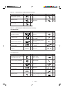
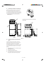
SYSTEM CONTROLLER IDENTIFICATION LABEL
ALL Central Control ALL RCU.
ZONE1 Central Control
ZONE1 RCU.
ZONE2 Central Control
ZONE2 RCU.
ZONE3 Central Control
ZONE3 RCU.
ZONE4 Central Control
*Please attach this label on surface of the lid after cleaning.
*If need to write down some detail, use magic marker.
ZONE4 RCU.
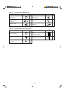
ALL ON
INPUT
ALL OFF
INPUT
COMMON
INPUT
COMMON
OUTPUT
OPERATION
STATE
OUTPUT
ALARM
OUTPUT
U1
U2
Inter-
unit
control
wiring
U2 Aux.
UNUSED
DC12V
FROM
INDOOR
UNIT PCB.