


22
22
2
K
28
S4359146
3-16.
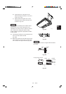
Wiring Instructions for Inter-Unit Connections
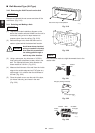
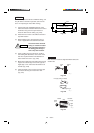
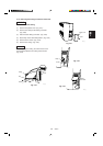
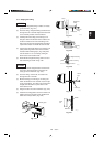
(a) Insert the inter-unit wiring (according to local
codes) into the through-the-wall PVC pipe. Run
the wiring toward the indoor side allowing approx.
5". to extend from the wall face. (Fig. 3-44)
Never fix the wiring by any
means before the indoor
unit is fully seated on the
rear panel.
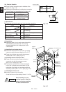
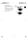
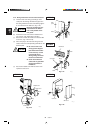
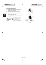
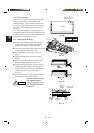
(b) Remove the side cover and the metallic cover.
(Fig. 3-45 or 3-46, depending on model.)
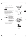
(c) Secure the conduit connector to the chassis with
a lock nut. (Fig. 3-45 or 3-46)
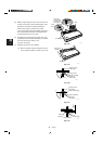
(d) Give some play to the inter-unit wiring from the
outdoor unit to the corresponding terminals on the
terminal plate.
● Be sure to refer to the
wiring system diagram
label inside the metallic
cover and carry out the
correct field wiring.
Wrong wiring can cause
the unit to malfunction.
● Check local electrical
codes and any specified
wiring instructions or
limitations.
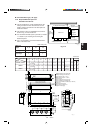
(e) Secure the metallic cover with its screw. Then
replace the side cover.
CAUTION
CAUTION
Wall
Plastic
cover
Rear
panel
Wiring
5"
1362_T_I
Fig. 3-45
Wall
Wall fixture
Connector Wiring
5"
1363_T_
I
Fig. 3-44
Fig. 3-46
Grounding
line
Power line
Screw
Plastic cover
Metallic cover
Lock
nut
Elbow
conduit
0968_T_I
Look nut
Lock
nut
Connector
Metallic cover
Side cover
1395_T_I
KH2442
KH3642
KH2442
KH3642