


47
S4359146
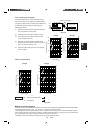
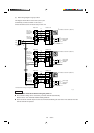
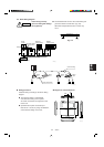
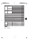
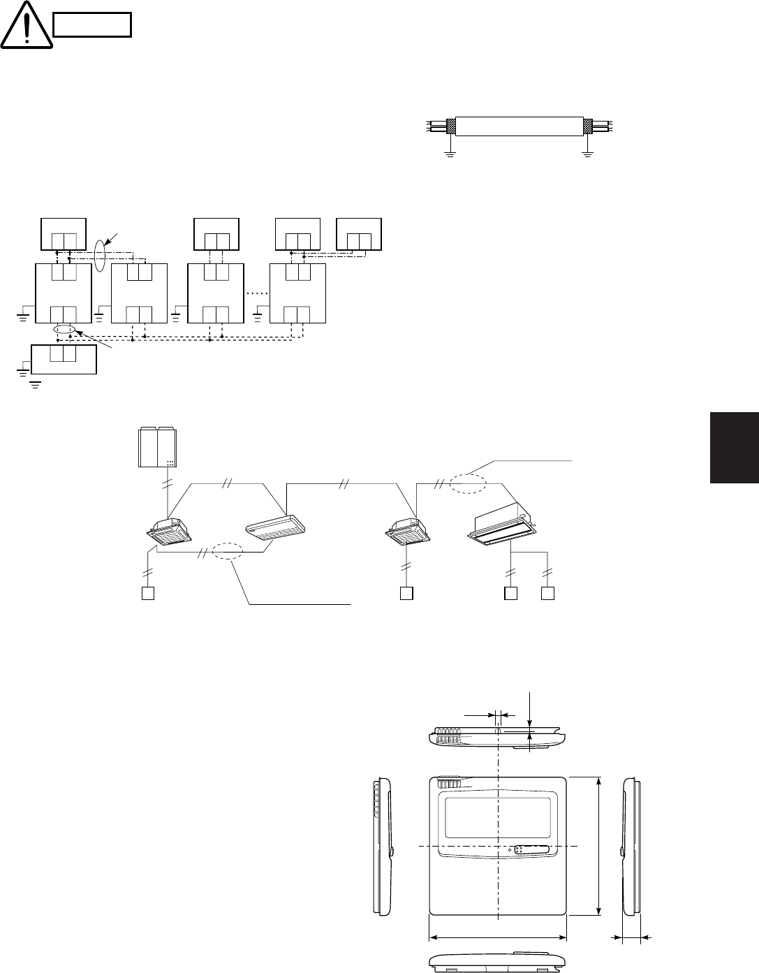
6-3. Basic Wiring Diagram
Install wiring correctly
(incorrect wiring will damage
the equipment).
CAUTION
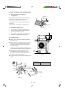
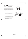
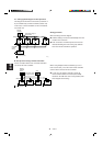
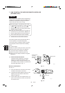
● Use shielded wires for inter-unit control wiring and
ground the shield on both sides. (Fig. 6-5)
Otherwise misoperation because of noise may
occur.
● Wiring procedure
Install the wiring according to the above wiring
diagram.
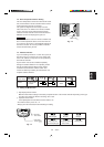
● The address setting is automatically
executed after turning on the system.
An indoor unit address is assigned to each
indoor unit.
● Operation takes place successively at
intervals of 1 second, by using combinations
of the address setting of each unit.
Shielded wire
0797_M_I
ground
ground
Fig. 6-5
2031_M_I
Inter-unit wiring
Group-control wiring
(Main) (Sub)
Indoor
unit 8
Indoor
unit 7
Indoor
unit 2
Indoor
unit 1
66
66
6
RC
(WD)
1
2
1
2
1
2
1
2
1
2
1
2
1
2
1
2
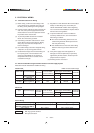
: Ground (earth)
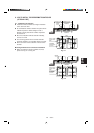
Outdoor unit
Indoor unit
No. 8
Indoor unit
No. 3
Indoor unit
No. 2
Indoor unit
No. 1
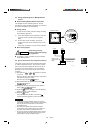
1
2
Group
control
Connection wiring
for group control
Standard
remote control
Multiple
remote control
2030_M_I
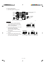
1
2
1
2
1
2
Inter-unit control wiring
Wire joint
1
2
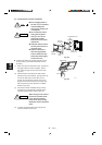
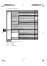
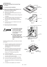
● Diagram of outer dimensions
5/32
4-23/32
5/8
3/32
4-23/32
1991_M_I