


77
77
7
RC
(WL)
66
S4359146
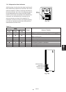
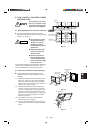
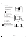
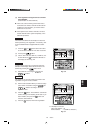
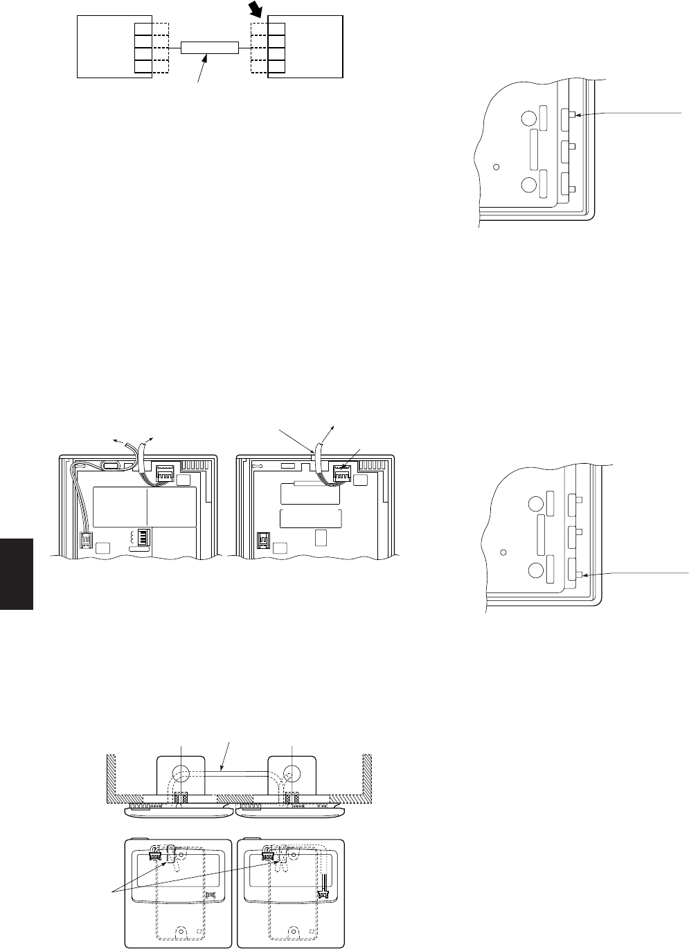
8-4. Test Run Setting
● After installation, check the output state of the
weekly timer with the “FORCED OPR.” switch
(OFF to ON) located on the rear side of its PCB.
After confirming normal operation, turn the
“FORCED OPR.” switch back to OFF without fail.
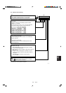
8-5. Memory Back Up Function for Power Failure
Compensation
● This weekly timer keeps the settings of operating
buttons memorized; so that after a power failure
the operation can be restarted in the same set
state by pressing the PROGRAM button.
● Using the “Back Up”
After installation, confirm that the BAT.BKUP
switch on the rear side of the weekly timer’s PCB is
ON.
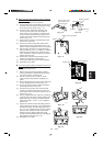
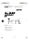
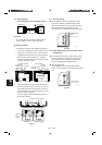
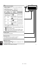
8-3. Wiring Diagram
(For wiring, always use the supplied wires)
● Layout
The weekly timer and remote controller may be
located, either one on the left or right sides.
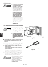
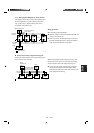
● Wiring procedure
Do the wiring according to the following procedure.
1 Loosen the retaining screw of the lead wire of the
weekly timer, remove the collar, and connect the
suppplied connection wiring to the timer terminal
(4P connector) of the weekly timer. Place the
supplied connection wiring into the groove neatly,
and then refasten the collar.
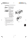
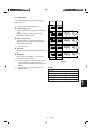
2 Pass the supplied connection wiring through the
lead-wire drawing-out port on the bottom case of
the weekly timer, then run it behind the wall and
connect it to the timer terminal (4P terminal) of the
remote controller. (Fig. 8-4)
(Use the supplied collar for fastening the wire of
the remote controller.)
Timer terminal
Weekly
timer
Remote
controller
or
System
controller
Connection wiring (supplied)
0806_M_I
1
2
3
4
1
2
3
4
1
2
3
4
1
2
3
4
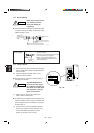
Timer terminal
2020_C_I
Lead wire
drawing
out port
<Weekly timer> <Remote controller>
Connection wiring (supplied)
88
88
8
WT
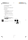
Fig. 8-5
Fig. 8-4
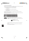
To weekly
timer
To remote
controller
Connector
To indoor unit
Remote control
cable terminal
board
<Remote controller>
2019_M_I
<Weekly timer>
Connection wiring
(supplied)
Fig. 8-6
FORCED OPR.
switch
PUL
ON OFF ON OFF
STA
2021_M_I
2022_M_
I
Back-up switch
PUL
ON OFF ON OFF
STA