


77
77
7
RC
(WL)
63
S4359146
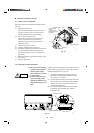
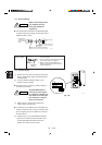
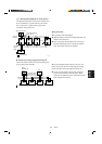
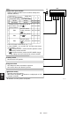
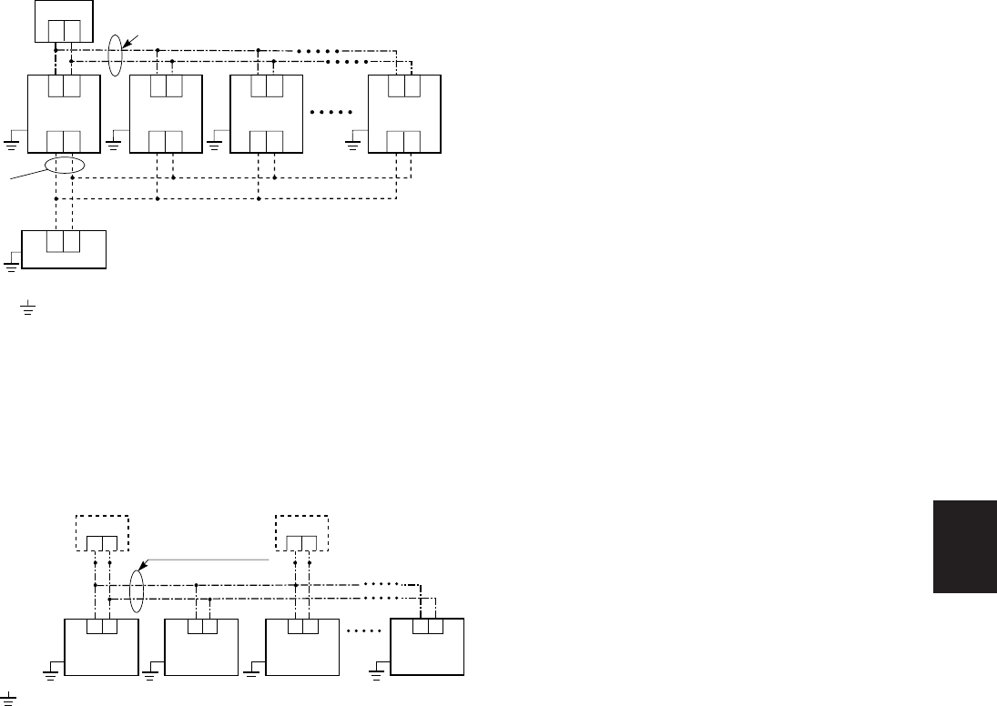
7-17. Wiring System Diagram for Group Control
This diagram shows when several units (maximum of
8) are controlled by a signal receiving unit (master
unit). In this case, a signal receiving unit can be
connected at any indoor unit.
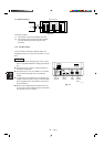
Wiring procedure
Wire according to the left diagram:
● Address setting is executed automatically when the
outdoor unit is turned on.
● Each successive unit will respond at one-second
intervals following the order of the group address
when the remote controller is operated.
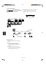
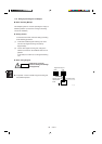
● Group control using 2 signal receiving unit.
It does not matter which of the 2 signal receiving unit
you set as the main controller.
When using multiple signal receiving unit (up to 2 of
them can be used), one is the main signal receiving
unit and the other is the sub-signal receiving unit.
● To set up a sub-signal receiving unit, change its
remote control address connector (RCU. ADR)
located on its PCB from main to sub position (main:
when shipped from factory).
(sub)
12
Wire joint
(2 wires)
Signal
receiving unit
(main)
2038_M_I
1
2
Indoor unit
No. 1
: Ground (earth)
Indoor unit
No. 2
Indoor unit
No. 8
Indoor unit
No. 3
Connection wiring
for group control
12
1
2
1
2
1
2
1
2
1
2
1
2
1
2
1
2
1
2
1
2
1
2
1
2
: Ground (earth)
Outdoor unit
Indoor unit
No. 8
Indoor unit
No. 3
Indoor unit
No. 2
Indoor unit
No. 1
1
2
Signal receiving unit
Connection wiring for
group control
2037_M_I
Inter-unit
control
wiring
Wire joint
(2 wires)