


11
11
1
X
16
S4359146
NOTE
CAUTION
CAUTION
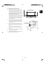
Fig. 3-11
Support
pieces
0050_X_
I
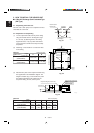
Fig. 3-10
Upward gradient
0049_X_
I
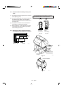
Fig. 3-9
Fig. 3-8
Air bleeder
0047_X_I
0197_X_I
Drain insulator (supplied)
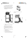
Fig. 3-7
Drain hose
(supplied)
Packing
(supplied)
Transparent part for
checking drainage
Hose band
(supplied)
Drain hose
adapter
(supplied)
Hard PVC pipe
(not supplied)
0964_X_I
Fig. 3-6
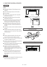
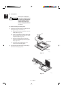
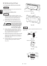
3-4. Installing the Drain Piping
(1) Prepare standard hard PVC pipe for the drain and
use the supplied drain hose and hose band to
prevent water leaks.
The PVC pipe must be purchased separately.
The transparent part allows you to check drain-
age. (Fig. 3-6)
Tighten the hose clamps
so their locking nuts face
upward. (Fig. 3-6)
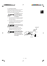
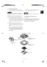
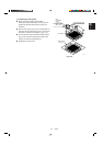
(2) After checking the drainage, wrap the supplied
packing and drain pipe insulator around the pipe.
(Fig. 3-7)
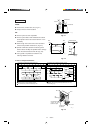
Ensure the drain pipe has a downward gradient
(1/100 or more) and that there are no water traps.
● Do not install an air
bleeder tubes, as this
may cause water to spray
from the drain tube outlet.
(Fig. 3-8)
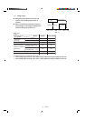
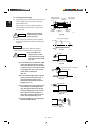
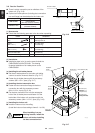
● If it is necessary to increase the height
of the drain pipe, the section directly
after the connection port can be raised
a maximum of 19-11/16 in. Do not raise
it any higher than 19-11/16 in., as this
could result in water leaks.
(Fig. 3-9)
● Do not install the pipe with an upward
gradient from the connection port. It
will cause the drain water to flow
backwards and leak when the unit is
stopped. (Fig. 3-10)
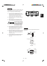
● Do not apply force to the piping on the
unit side when connecting the drain
pipe. The pipe should not be allowed
to hang unsupported from its connec-
tion to the unit. Fasten the pipe to a
wall, frame, or other support as close
to the unit as possible. (Fig. 3-11)
● Provide insulation for any drain pipes
that are installed indoors.
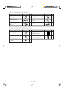
11-3/4 in. or less (as short as possible)
19-11/16 in. or less
1972_X_I