


42
S4359146
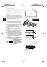
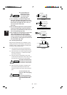
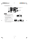
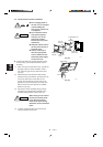
5-3. Wiring System Diagrams
(1) Basic wiring diagram for standard control
1
2
U1
U2
1
2
1
2
1
2
1
2
G G
L1
L2
G
Indoor Unit
Inter-unit
power wiring
Single phase
230/208V
Inter-unit
control wiring
(Low voltage)
Remote controller
Outdoor Unit
Ground
Ground
(Option)
B
D
A
2085_M_I
Power supply
Single phase
230/208V
R.C. Address on the PCB: 0 (S2, BLK)
(0: Factory shipped state)
L1
L2
U1
U2
0
C
*Remote controller wirings are wire joint connection.
NOTE
(1) Refer to Section 5-2. “Recommended Wire
Length and Wide Diameter for Power Supply
System” for the explanation of “A”, “B”, “C”, “D”,
and “E”, in the above diagrams.
(2) Inter-Unit Control Wiring (C) and remote control-
ler wiring (D), (E) has no polarity.
But for other wiring, respect polarity.
Be sure to connect as shown in the Wiring
System Diagram.
(3) R.C. Address should be set before turning the
power on.
(4) Regarding the R.C. Address setting, refer to
page 87. Auto. address setting can be executed
by a remote controller automatically.
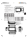
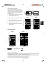
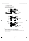
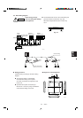
G
L2L1
12
Power
supply
5P terminal board + 2P terminal board
2086_M_I
CH Type
U1
Inter-unit
control wiring
Inter-unit
power wiring
U2
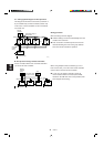
12
Inter-unit
power wiring
U1
Inter-unit
control wiring
U2
5P terminal board
2087_M_I
XH, TH, UH Type
Inter-unit
control wiring
4P terminal board
2088_M_I
12
Inter-unit
power wiring
U1 U2
KH Type
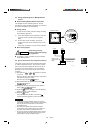
3003_M_I
Remote
controller wiring
3003_M_I
Remote
controller wiring