


43
S4359146
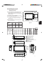
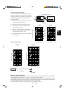
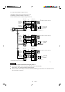
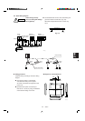
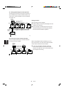
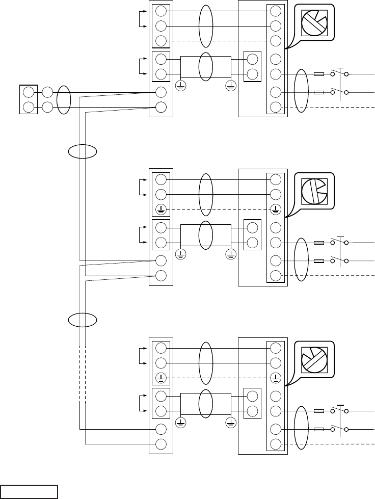
(2) Basic wiring diagram for group control
This diagram shows when several units (max. 8) are
controlled by a remote controller. In this case, a
remote controller can be connected at any indoor unit.
● R.C. Address should be set before turning the power on.
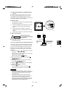
● Auto. address setting can be executed by a remote controller automatically.
Please refer to 12-4 “Automatic Address Setting Method”.
● Each successive unit will respond at one-second intervals following the order of the R.C. address when the
remote controller is operated.
NOTE
1
2
U1
U2
11
2
1
2
1
2
G G
4
L1
L2
G
Indoor Unit
Inter-unit
power wiring
single phase
230/208V
Inter-unit
control wiring
(Low voltage)
RED
BLK
Remote controller
Outdoor Unit
Ground
Ground
(Option)
B
D
A
A
A
E
2089_M_I
Power supply
single phase
230/208V
*1
R.C. Address on the PCB: 1 (S2, BLK)
L1
L2
U1
U2
1
1
2
U1
U2
1
2
1
2
4
L1
L2
G
Indoor Unit
Inter-unit
power wiring
single phase
230/208V
Inter-unit
control wiring
(Low voltage)
Outdoor Unit
Ground
Ground
B
E
Power supply
single phase
230/208V
Power supply
single phase
230/208V
R.C. Address on the PCB: 2 (S2, BLK)
L1
L2
U1
U2
2
1
2
U1
U2
1
2
1
2
4
L1
L2
G
Indoor Unit
Inter-unit
power wiring
single phase
230/208V
Inter-unit
control wiring
(Low voltage)
Outdoor Unit
Ground
Ground
B
R.C. Address on the PCB: 8 (S2, BLK)
L1
L2
U1
U2
8
C
C
C
*Remote controller wirings are wire joint connection.
2