


44
44
4
U
S4359146
35
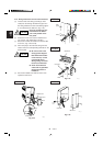
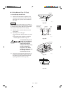
■ Concealed-Duct Type ( UH Type)
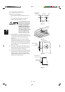
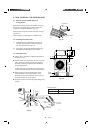
3-22. Required Minimum Space for
Installation and Service
● This air conditioner is usually installed above the
ceiling so that the indoor unit and ducts are not
visible. Only the air intake and air outlet ports are
visible from below.
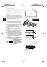
● The minimum space for installation and service is
shown in Fig. 3-72 and Table 3-3.
● It is recommended that space is provided (17-23/32
× 17-23/32 in.) for checking and servicing the
electrical system.
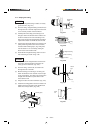
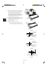
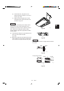
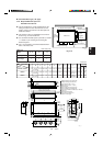
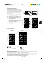
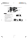
● Fig. 3-73 and Table 3-4 show the detailed dimen-
sions of the indoor unit.
Fig. 3-73
Table 3-3
Type
A (Length)
Number of
duct flanges
36
61-13/32 (1,560)
4
12, 18
30-23/32 (780)
2
ABCDEFG HIJK
26-1/16
23-5/8
27-9/16 30-23/32 11-13/32 10-5/16 26-25/32 28-5/32 7-3/32 – 13-3/8 8 12
(7-7/8×3)
37-7/8
35-7/16
39-3/8 42-17/32 11-13/32 10-23/32 38-19/32 39-31/32 5-1/8
9-21/32
9-27/32 12 16
(7-3/32×5)
(9-21/32×1)
56-25/32
54-11/32
58-9/32 61-13/32 13-3/16 12-7/32 57-15/32 58-27/32 5-1/8
19-9/32
9-7/16 16 18
(9-1/16×6) (9-21/32×2)
Refrigerant tubing joint (narrow tube)
Refrigerant tubing joint (wide tube)
Upper drain port (O.D. 1-1/4 in.)
Bottom drain port (O.D. 1-1/32 in.)
Suspension lug
Power supply outlet (2-ø1-3/16 hole)
Fresh air intake port (ø5-29/32 hole)
Flange for the flexible air outlet duct (ø7-7/8 hole)
Tube cover
Electrical component box
Flange for the air intake duct
(Option or field supply)
9
10
9
10
11
1978_U_I
11
(Suspension bolt pitch)
(Suspension bolt pitch)
M-ø1/8
(Hole)
4-ø15/32
(Hole)
(Hole)
A (O.D.)
L-ø1/4
I
13/32
13/32
13/32
2-5/322-5/32 7-7/8
13/32
IJJK
B
C
D (5-29/32)
1-9/16
E E E F 2-15/16
2-9/16
11-7/32
2-3/4
5-1/8
31/32 8-9/32
12-7/32
31/32
6-7/8
1-3/8
3-17/32
1-7/321-7/32
H (Duct suspension bolt pitch)
G (Ceiling opening dimension)
31/32
3-15/16
7-9/32
22-27/3231/32
4-17/32
7-15/32
3-11/32
31/32
2-3/4 1-3/16
6-5/16
24-13/16 31/32
13/32
3-15/32
10-13/16
(Ceiling opening dimension)
10-1/4
(O.D.)
3/43/4
Inspection access
(17-23/32
×
17-23/32)
(Field supply)
Inspection access panel
Ceiling
24
42-17/32 (1,080)
3
Unit: inch (mm)
Unit: inch
Table 3-4
Dimension
Type
UH1242, UH1842
UH2442
UH3642
1977_U_I
Indoor Unit
Inspection
access
17-23/32
×
17-23/32
Air outlet duct flange
min.
9-27/32
min.
15-3/4
min. 25-19/32
22-27/32
A (Suspension bolt pitch)
Electrical
component box
Refrigerant
tubing
Unit: inch
min.
9-27/32
Fig. 3-72
No. of holes
LM