


46
S4359146
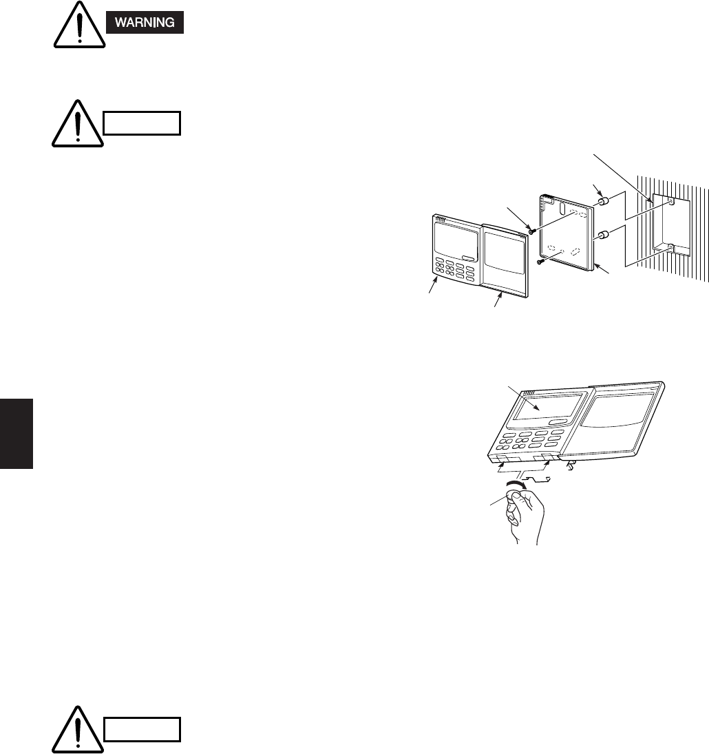
Fig. 6-3
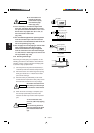
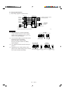
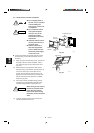
6-2. Wired Remote Controller Installation
● Do not supply power to
the unit or try to operate it
until the tubing and
wiring to the outdoor unit
is completed.
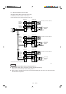
● Do not twist the control
wiring with the power
wiring or run it in the
same metal conduit,
because this may cause
malfunction.
● Install the remote control-
ler away from sources of
electrical noise.
● Install a noise filter or
take other appropriate
action if electrical noise
affects the power supply
circuit of the unit.
● If local codes allow, this remote controller can be
mounted using a conventional wall box for flush
mounting.
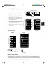
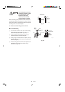
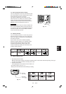
(1) When you open the decorative cover, you will see
two gaps under the remote controller. Insert a
coin into these gaps and pry off the back case.
(Fig. 6-4)
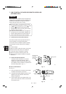
(2) Attach the back case with the 2 small screws
provided. Using a screwdriver, push open the cut-
outs on the back case. These holes are for
screws. Use the spacers and take care not to
tighten the screws excessively. If the back case
will not seat well, cut the spacers to a suitable
thickness. (Fig. 6-3)
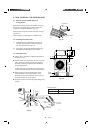
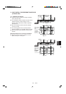
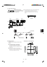
(3) Connect the remote controller wiring (2 wires)
correctly to the corresponding terminals in the
electrical component box of the indoor unit.
When wiring, do not connect
the remote controller wires
to the adjacent terminal
block for the power wiring.
Otherwise, the unit will break
down.
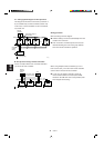
(4) To finish, fit the back tabs of the case into the
remote controller and mount it.
CAUTION
66
66
6
RC
(WD)
Fig. 6-4
CAUTION
1989_C_I
Wired remote
controller
Decorative
cover
Concealed box for 1
Spacer
M4 × 25
Screws (2)
Under case
(Back case)
Gap
Coin
1990_M_I
Gap
Control panel