


77
77
7
RC
(WL)
65
S4359146
8.
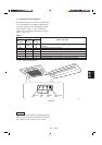
HOW TO INSTALL THE WEEKLY TIMER
(
OPTIONAL PART
)
Do not supply power to the
unit or try to operate it until
the tubing and wiring to the
outdoor unit is completed.
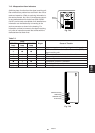
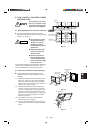
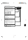
8-1.
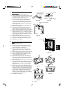
Mounting Dimensions for Continuous Installation
● For vertical continuous installation, the space
between the weekly timer and the remote controller
must be 1 in. or more.
● Do not twist the control
wiring with the power
wiring or run it in the
same metal conduit,
because this may cause
malfunction.
● Install the weekly timer
away from sources of
electrical noise.
● Install a noise filter or
take other appropriate
action if electrical noise
affects the power supply
circuit of the unit.
The mounting position for the weekly timer should be
located in an accessible place for control. Never
cover the weekly timer or recess it into the wall.
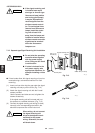
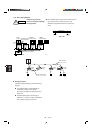
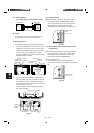
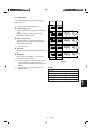
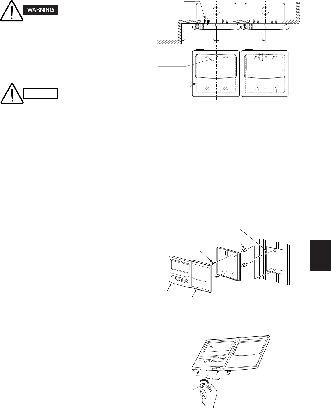
8-2. When Using a Wall Box for Flush Mounting
● If local codes allow, this weekly timer can be
mounted using a conventional wall box for flush
mounting.
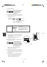
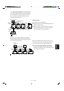
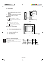
(1) Remove the flat-top screw on the bottom of the
back case. When you open up the decorative
cover, you will see two gaps under the weekly
timer. Insert a coin into these gaps and remove
the back case. (Figs. 8-2, 8-3)
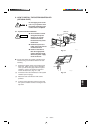
(2) Attach the back case with the 2 small screws
provided. Using a screwdriver, push open the
cut-outs on the back case. These holes are for
screws. Use the spacers and take care not to
tighten the screws excessively. If the back case
does not sit well, cut the spacers to a suitable
thickness. (Fig. 8-2)
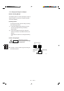
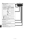
(3) Connect the 4 wires to the weekly timer 4P
terminal base (see next page).
(4) To finish, fit the back tabs of the back case into
the weekly timer and mount it using the flat-top
screw.
CAUTION
2016_C_I
Spacer
3-17/32 in. or more
4-29/32 in. or more
Wall
Wiring outlet
Switch box
Fig. 8-1
Fig. 8-2
2017_C_I
Weekly
timer
Decorative
cover
Concealed box
Spacer
M4 × 31/32 in.
Screws (2)
88
88
8
WT
Fig. 8-3
Gap
Coin
2018_M_I
Gap
Control panel