


11
S4359146
99
99
9
SC
11
11
1
X
88
88
8
WT
77
77
7
RC
(WL)
55
55
5
C
44
44
4
U
33
33
3
T
22
22
2
K
66
66
6
RC
(WD)
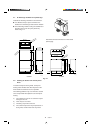
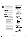
Out-
door
unit
Heat source
Hot air
Exhaust fan
0591_C_I
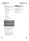
Outdoor Unit
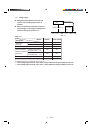
AVOID:
● heat sources, exhaust fans, etc. (Fig. 2-1)
● damp, humid or uneven locations.
DO:
● choose a place as cool as possible.
● choose a place that is well ventilated and outside
air temperature does not exceed maximum 115°F
constantly.
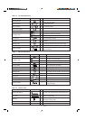
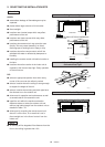
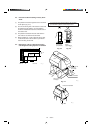
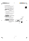
● allow enough room around the unit for air intake/
exhaust and possible maintenance. (Fig. 2-2)
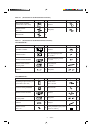
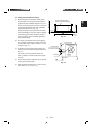
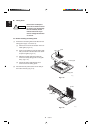
● provide a solid base; about 6 inch above ground
level to reduce humidity and possible water damage
in the unit and decreased service life. (Fig. 2-3)
● use lug bolts or equivalent to bolt down unit,
reducing vibration and noise.
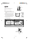
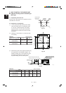
In case of multiple installations
Fig. 2-1
Fig. 2-2
Min.
1 inch
Min.
1 inch
Min. 2 ft.
4 in.
0931_C_I
Min.
7 ft.
Ground
Air
dis-
charge
0932_C_I
Obstacle above
Unit spacing if air discharge chamber is not used. Unit spacing when air discharge chamber is used.
Min. 4 ft. Min. 4 ft.Min. 5 ft.
Min. 1 ft.
Min. 12 ft.
Min. 8 inch
Min. 4 ft.
Min. 8 inch
Min. 4 ft.
Min. 1 ft. 2 inch
Min. 1 ft. 2 inch
Min. 1 ft.
Min. 1 ft.
Air
discharge
chamber
If you would like to make the separation smaller on the air
discharge side, use an air discharge chamber.
You can install any number of units side-by -side.
Only up to 3 units can be installed side-by-side under the above
conditions. The next group must be spaced at least 1 ft. away
from the first group.
0933_C_S
Fig. 2-3
Air in
Air in
Air
discharge
Concrete block
4 inch × 1 ft. 4 inch
beams or equal
Anchor bolts
(4 pieces)
Min. 6 inch
0934_C_I