


77
77
7
RC
(WL)
56
S4359146
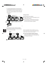
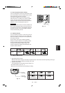
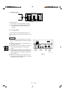
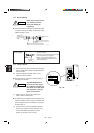
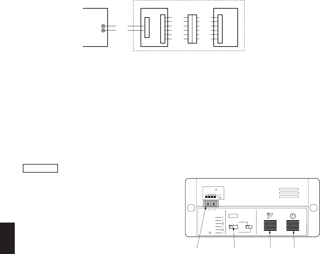
7-9. Electrical Wiring
Connection method
(1) Connect W1 to the indoor PCB WL connector.
(2) Connect W3 from the indicator section with W2
from the operating controller using the relay
connector.
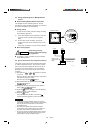
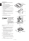
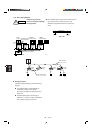
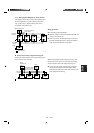
7-10. Test Run Switch
Test run switch is located at operating control unit.
Regarding the test run, please refer to section 12. Test
Run.
● In case of 4-way air discharge type, test run opera-
tion is not possible without the ceiling panel installa-
tion.
● During the test run, all of the 3 indicator lamps on
the indoor unit will flash.
● During the test run, the air conditioner runs continu-
ously and the thermostat does not control the
system.
● To protect the air conditioner from overloading, the
outdoor unit will not start running for 3 minutes after
power is applied or the air conditioner is turned off
and then back on.
● When the air conditioner fails to start the test run, 1
or more of the 3 alarm indicator lamps on the indoor
unit will flash (See next section).
Fig. 7-10
WHT
BLK
1
2
W1 (4.3 ft.)
WL
Indoor PCB Operating controller
Signal receving unit
2035_M_I
Indicator section
W2
(0.7 ft.)
W3
(4.3 ft.)
CN1
CN2
Relay connector
CN1
BLU
YEL
PNK
RED
GRY
BLK
BLU
YEL
PNK
RED
GRY
BLK
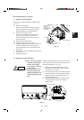
NOTE
1
1
ADR
1.TEST RUN
2.PCB CHK.
3.RCU: MAIN
RCU: SUB
4.NORMAL
ALL •
Servicing
switches
Address
switch
ON/OFF
operation
button
1999_M_I
All OFF( ) for
initial settings.
234
2 3
456
Flap
button
Fig. 7-11