


Page
CONTENTS
IMPORTANT
Please Read Before Starting
1. GENERAL ................................................................... 4
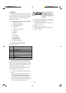
1-1. Tools Required for Installation (Not Supplied)
1-2. Accessories Supplied with Unit
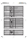
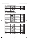
1-3. Type of Copper Tube and Insulation Material
1-4. Additional Materials Required for Installation
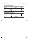
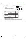
1-5. Tubing Length
2. SELECTING THE INSTALLATION SITE .................. 10
Indoor Unit
Outdoor Unit
2-1. Air Discharge Chamber for Top Discharge
2-2. Installing the Outdoor Unit in Heavy Snow Areas
2-3. Precautions When Installing in Heavy Snow Areas
2-4. Dimensions of Snow / Wind-proof Ducting and
Refrigerant Tubing Space for Installation
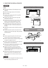
3. HOW TO INSTALL THE INDOOR UNIT .................... 14
■ 4-Way Air Discharge Semi-Concealed Type
(XH Type)................................................................... 14
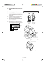
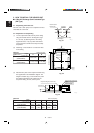
3-1. Suspending the Indoor Unit
3-2. Preparation for Suspending
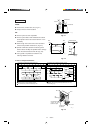
3-3. Placing the Unit Inside the Ceiling
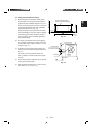
3-4. Installing the Drain Piping
3-5. Checking the Drainage
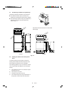
3-6. Before Installing the Ceiling Panel
3-7. Installing the Ceiling Panel
3-8. When Removing the Ceiling Panel for Servicing
3-9. Duct for Fresh Air
■ Wall-Mounted Type (KH Type) ................................... 22
3-10. Removing the Wall Fixture from the Unit
3-11. Selecting and Making a Hole
3-12. Installing the Wall Fixture onto Wooden or
Gypsum Wall
3-13.
Removing the Casing to Install the Indoor Unit
3-14. Preparing the Indoor Side Tubing
3-15. Wiring Instructions
3-16.
Wiring Instructions for Inter-Unit Connections
3-17. Shaping the Tubing
3-18. Installing the Drain Hose
■ Ceiling-Mounted Type (TH Type). .............................. 31
3-19. Suspending the Indoor Unit
3-20. Duct for Fresh Air
3-21. Installing the Drain Piping
■ Concealed-Duct Type (UH Type) ............................... 35
3-22.
Required Minimum Space for Installation and Service
3-23. Suspending the Indoor Unit
3-24. Installing the Drain Piping
Page
3-25. Checking the Drainage
3-26. Increasing the Fan Speed
4. HOW TO INSTALL THE OUTDOOR UNIT ................ 40
4-1. Removing the Protective Spacer for Transportation
4-2. Installing the Outdoor Unit
4-3. Tubing Direction
5. ELECTRICAL WIRING ............................................. 41
5-1. General Precautions on Wiring
5-2. Recommended Wire Length and Wire Diameter
for Power Supply System
5-3. Wiring System Diagrams
5-4. How to Connect Wiring to the Terminal
6.
HOW TO INSTALL THE WIRED REMOTE CONTROLLER
(OPTIONAL PART) .................................................... 45
6-1. Installation site selection
6-2. Wired Remote Controller Installation
6-3. Basic Wiring Diagram
6-4. Wiring System Diagram for Group Control
6-5. Wiring System Diagram for Multiple Remote
Control
6-6. How to Switch the Indoor Temperature Sensor
6-7. Explanation of Alarm Messages
7.
HOW TO INSTALL THE WIRELESS REMOTE CONTROLLER
(OPTIONAL PART) .................................................... 52
7-1. Wireless Remote Controller Installation
7-2. Room Temperature Sensor Setting
7-3. Address Switches
7-4. Setting the Model Code
<RCS-SH80UA. WL>
■ 4-Way Air Discharge Semi-concealed Type
(XH Type)................................................................... 54
7-5. Indicator section Installation
7-6. Operating Controller Installation
■ Ceiling Mounted Type (TH Type)......................... 55
7-7. Indicator Section Installation
7-8. Operating Controller Installation
7-9. Electrical Wiring
7-10. Test Run Switch
7-11. Misoperation Alarm Indicators
<RCS-BH80UA.WA>
7-12.
Separate type Signal Receiving Unit Installation
7-13. Electrical Wiring
7-14. Test Run Switch
7-15. Misoperation Alarm Indicators
7-16. Basic Wiring Diagram
7-17. Wiring System Diagram for Group Control
7-18. Wiring System Diagram for Multiple