


77
77
7
RC
(WL)
58
S4359146
<RCS-BH80UA.WA>
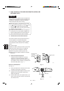
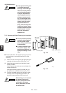
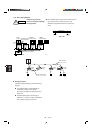
● If the signal receiving unit
is installed near rapid-
start type or inverter type
fluorescent lamp (neither
one having glow lamps),
it may be impossible to
receive signals from the
wireless remote control-
ler. To avoid signal inter-
ference from fluorescent
lamps, install the receiv-
ing unit at least 6.6 ft.
away from the lamps and
install at a location where
wireless remote controller
signals can be received
when the fluorescent
lamps are on.
7-12.
Separate type Signal Receiving Unit Installation
● Do not twist the operating
controller wires together
with the power supply
wires. Doing so can result
in malfunction.
● If noise is induced in the
unit power supply, take
appropriate measures, for
example installing a noise
filter.
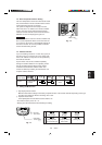
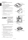
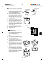
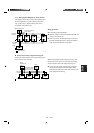
● If local codes allow, this signal receving unit can be
mounted using a conventional wall box for flush
mounting.
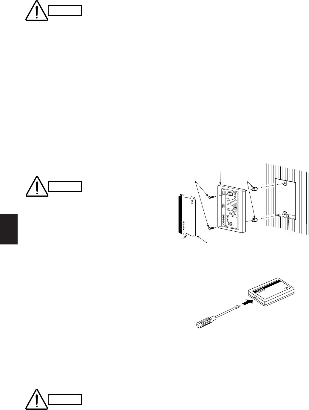
(1) Insert a minus driver into the gap under the signal
receving unit and pry off the cover (Fig. 7-14)
(2) Attach the signal receving unit with the 2 small
screws provided.
Use the spacers and take care not to tighten the
screws excessively.
If the signal receving unit will not seat well, cut
the spacers to a suitable thickness. (Fig. 7-13)
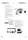
(3) Connect the signal receving unit wiring (2 wires)
correctly to the corresponding terminals in the
electrical component box of the indoor unit.
When wiring, do not connect
the signal receving unit
wires to the adjacent termi-
nal block for the power
wiring. Otherwise, the unit
will break down.
CAUTION
2002_M_I
2001_M_I
Cover plate
Notch
Spacer
Switch box (no cover)
Signal receiving unit
M4 × L1 in
Screws (2)
1
2
3
4
ADR
56
ALL•
RCU : SUB
RCU : MAIN
NORMAL
PCB CHK.
TEST RUN
Fig. 7-13
Fig. 7-14
CAUTION
CAUTION