


33
33
3
T
31
S4359146
■ Ceiling-Mounted Type (TH Type)
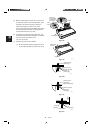
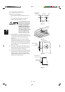
3-19. Suspending the Indoor Unit
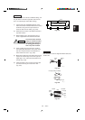
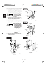
(1) Place the full-scale diagram (supplied) on the
ceiling at the spot where you want to install the
indoor unit. Use a pencil to mark the drill holes.
(Fig. 3-55).
Since the diagram is made of paper, it may shrink or
stretch slightly because of high temperature or humid-
ity. For this reason, before drilling the holes maintain
the correct dimensions between the markings.
(2) Drill holes at the 4 points indicated on the full-
scale diagram.
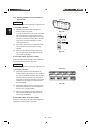
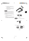
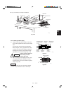
(3) Depending on the ceiling type:
a) Insert suspension bolts as shown in Fig. 3-56.
or
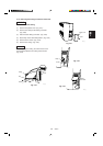
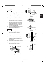
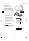
b) Use existing ceiling supports or construct a
suitable support as shown in Fig. 3-57.
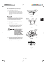
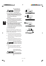
It is important that you use
extreme care in supporting
the indoor unit from the
ceiling. Ensure that the
ceiling is sufficiently strong
enough to support the
weight of the unit. Before
hanging the ceiling unit, test
the strength of each at-
tached suspension bolt.
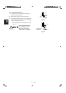
(4) Screw in the suspension bolts, allowing them to
protrude from the ceiling as shown in Fig. 3-57.
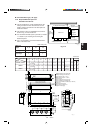
The distance of each exposed bolt must be of
equal length within 2 inches. (Fig. 3-58)
NOTE
Fig. 3-55
Fig. 3-58
unit
Ceiling
surface
Fixture
0971_T_I
Within 2 in.
Fig. 3-57
Ceiling tiles
Ceiling support
0084_T_I
A
A
Fig. 3-56
Hole-in-anchor
Hole-in-plug
Concrete Insert
Suspension bolt (M10 or 3/8")
(field supply)
0038_T_I
Rear
Full-scale diagram
Front face
0035_T_I