


6
MITSUBISHI ELECTRIC
FR-F 740 EC/E1
Extended PID control
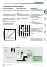
The FR-F 740 series supports extended PID
control. This feature makes it possible to
connect the process status signal to the fre
-
quency inverter as a voltage signal
(0–10 V DC) or a current signal
(0/4–20 mA DC) and then use the analog
input calibration function of the inverter to
compensate minor controller-related fluc
-
tuations.
In addition to this the frequency inverter
can also control up to four motors succes
-
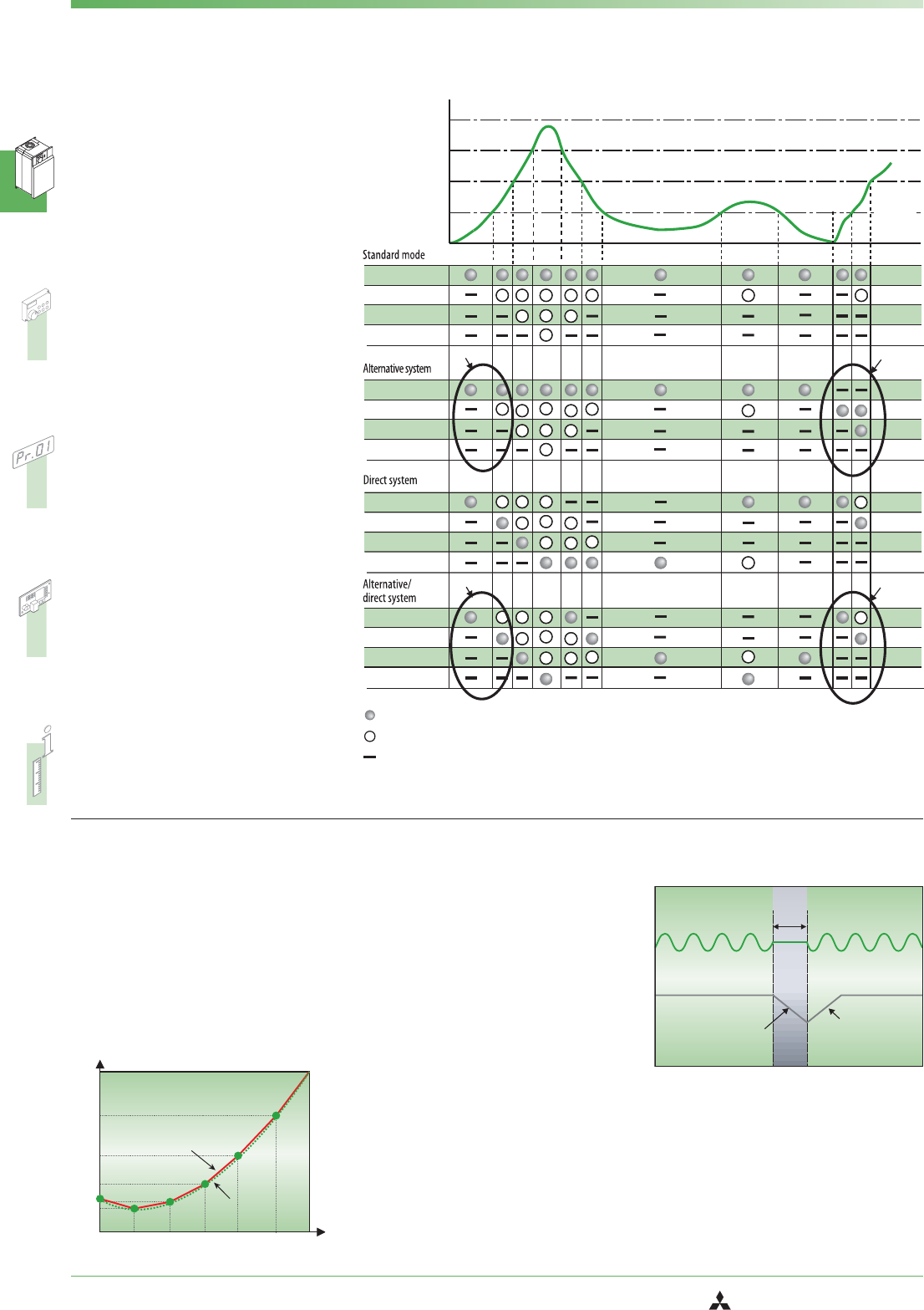
sively. This function is programmable; for
example, you can program it so that only
one motor is frequency-controlled and the
others are switched on and off under direct
mains power as required, or you can alter
-
nate between direct mains power and
frequency control for all four motors.
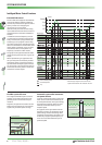
The graph on the right illustrates this multi-
motor switching function with a typical ex
-
ample.
When implementing an application like
this you must plan the necessary number
of magnetic power contactors and the re-
quired number of output signal terminals
on the inverter. Care must also be taken to
ensure that the mains power is never swit-
ched to the inverter output.
Motor 1 (M1)
Motor 2 (M2)
Motor 3 (M3)
Motor 4 (M4)
Motor 1 (M1)
Motor 2 (M2)
Motor 3 (M3)
Motor 4 (M4)
Motor 1 (M1)
Motor 2 (M2)
Motor 3 (M3)
Motor 4 (M4)
Motor 1 (M1)
Motor 2 (M2)
Motor 3 (M3)
Motor 4 (M4)
*2
*1
*2
*1
Q max
Q3
Q2
Q1
Inverter controlled operation
Conventional operation
Stop
Time
*
*
Flow rate
* After switching the magnetic contactor the motor start
sequence switches from M1->M2->M3 to M2->M3->M1
Intelligent Motor Control Functions
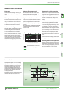
Flexible 5-point V /f curve
The integrated flexible 5-point V/f curve
enables you to match the torque curve
perfectly to the characteristics of your
machine.
Together, the optimum excitation control
feature and the 5-point V/f curve achieve
significantly increased power savings.
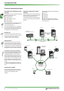
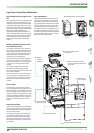
Automatic restart after instantane
-
ous power failures
In pump and fan applications normal ope
-
ration can be continued automatically af
-
ter brief power failures. The system simply
reactivates the coasting motor and auto
-
matically accelerates it back up to its
setpoint speed.
The graphic on the right shows how the
frequency inverter can respond to a brief
power outage. Instead of coasting down
completely and stopping, the motor is au
-
tomatically “caught” by the frequency in
-
verter and re-accelerated back up to its
previous speed.
0
V/F5
V/F4
V/F3
V/F2
V/F1
Base frequency
V/f pattern
Torque
characteristic
Voltage
V/f characteristic
IPF
Restart
acceleration
Deceleration
Power supply
Output frequency
SYSTEM DESCRIPTION