


29
MITSUBISHI ELECTRIC
FR-F 740 EC/E1
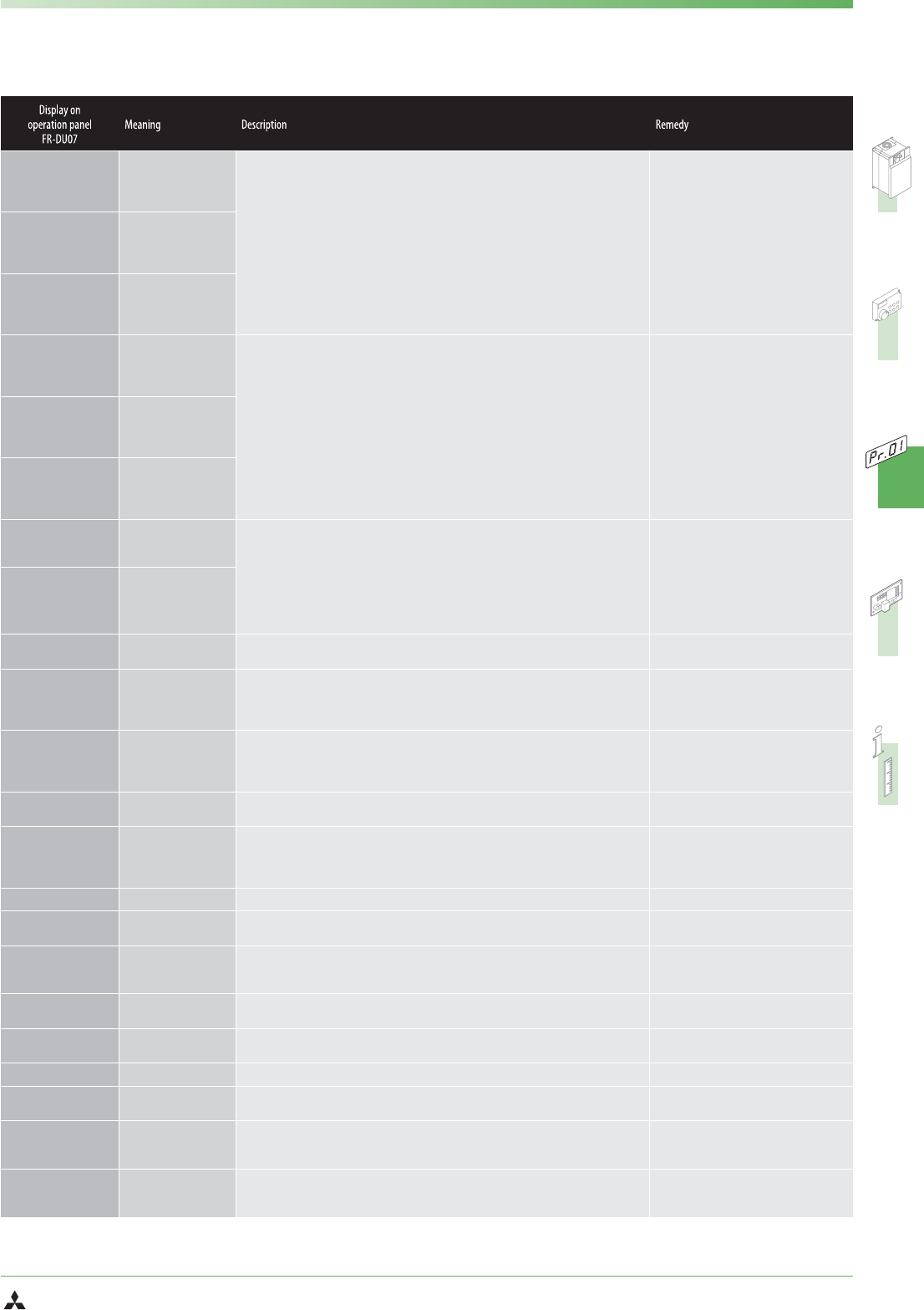
PROTECTIVE FUNCTIONS
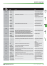
E.OC1
Overcurrent 1
(acceleration)
The output current of the inverter has reached or exceeded 200% of the rated current during the ac
-
celeration,deceleration,or at constant speed.
The cause for the activation of the protective
function is a short circuit or a ground fault
across the main outputs,an exceeding moment
of inertia of the load (GD
2
),too short accelera
-
tion / deceleration time presets,restart during a
motor idling phase,operation of a motor with
an exceeding capacity.
Overheating due to insufficient cooling (defec
-
tive cooling fan or choked heat sink).
E.OC2
Overcurrent 2
(const.speed)
E.OC3
Overcurrent 3
(deceleration)
E.OV1
Overvoltage 1
(acceleration)
The converter voltage has increased highly due to regenerative energy.The overvoltage limit was
exceeded during acceleration,deceleration,or at constant speed.
In most cases the protective function is acti
-
vated due to a too short deceleration time
preset or a regenerative overload.
Remedy by increasing the deceleration time of
connecting an external brake unit.
An overvoltage in the mains power supply
activates this protective function as well.
E.OV2
Overvoltage 2
(constant speed)
E.OV3
Overvoltage 3
(deceleration)
E.THM
Motor overload shutoff
The electronic overload protection for the motor or inverter was activated.
The electronic motor protection switch continually detects the motor current and the output fre-
quency of the inverter.If a self-cooling motor operates over a long period at low speed but high
torque,the motor is thermally overloaded and the protective function is activated.
If several motorsare operated by oneinverter the motorprotectionswitch will notoperate properly.
In this case deactivate the motor protection and replace it by external protection switches.
Decrease the motor load to avoid an activation.
Check whether the performance range of the
motor and inverter correspond.
E.THT
Inverter overload shutoff
E.FIN
Fin overheat
In case of an overheating of the heat sink the temperature sensor responds and the inverter is
stopped.
Check ambient temperature.
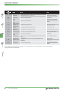
E.IPF
Instantaneous
power failure protection
The output of the inverter is suspended and the alarm message returned,if the power supply fails
for more than 15 ms.If the power supply fails for more than 100 ms,the inverter shuts down com-
pletely.In this case after restoring the power supply the inverter is in the power ON state.If the
power failure stays below 15 ms,the operation is proceeded normally.
Check the power supply.
E.UVT
Undervoltage protection
The input voltage of the inverter has fallen below the minimum value.The protective function is ac
-
tivated,if the input voltage falls below the minimum value.
An undervoltage can occur,if the capacity of
the mains transformer is not sufficient or if a
high capacity motor is turned ON connected to
the same mains supply circuit.
E.ILF
ቢ
Input phase failure Open phase at power supply input.
Check the power supply connections and the
mains fuse!
E.OLT
Stall prevention
overload
A long lasting excess of the current limit (OL display) shut down the inverter.
Reduce the load.
Check the preset values for the current limit
(parameter 22) and the stall prevention
selection (parameter 156).
E.GF
Ground failure Anovercurrentoccuredduetoagroundfailureuponthe inverteroutput(load). Check load connections (motor circuit).
E.LF
Output phase failure
protection
One of the phases (U,V,W) is not connected. Check the connections.
E.OHT
Activation of an external
motor protection relay
(thermal contact)
An external motor protective switch was activated.
If an external motor protective switch for thermal monitoring is used,this switch can activate the
protective function of the inverter.
Leitungen und Anschlüsse am Eingang prüfen
E.PTC
ቢ
PTC thermistor operation
The frequency inverter has shut down because the resistance of the PTC thermistor has exceeded
the permitted 500Ω–4kΩrange for 10s.
Check the PTC connection.Check motor opera
-
tion under load.Check setting of Pr.184.
E.OPT
Option alarm
This error is displayed when an FR-HC,MT-HC or FR-CV external optional unit is installed and the
power supply is still connected via terminals L1,L2 and L3.
Check the setting of Pr.30 and the installation
and connections of the optional unit.
E.OP1
Option slot alarm The protective function is activated for a fault (e.g.transmission error) of an internal optional unit. Checkthe function settings of the optional unit.
E.1
Option alarm (e.g.con
-
nection or contact fault)
This protective function is activated when an error (e.g.a contact fault) is registered in the installed
optional unit.
Check the connections of the optional unit.
Check for electromagnetic interference.
E.PE
Parameter storage device
alarm (control circuit
board)
Error on access of the data memory of the inverter.
Please contact your nearest MITSUBISHI
ELECTRIC representative if the error occurs
repeatedly.
E.PE2
ቢ
Parameter storage device
alarm (main circuit board)
Error on access of the data memory of the inverter.
Please contact your nearest MITSUBISHI
ELECTRIC representative if the error occurs
repeatedly.