


27
MITSUBISHI ELECTRIC
FR-F 740 EC/E1
611
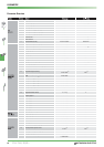
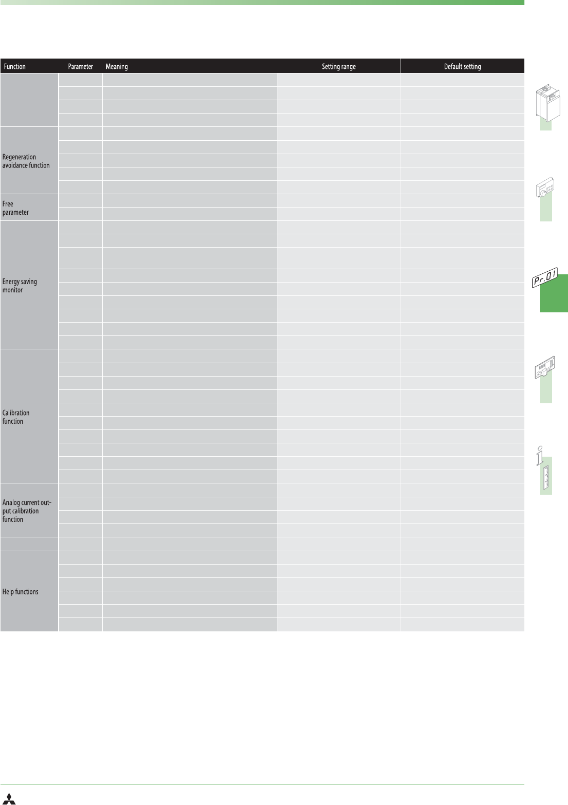
Acceleration time at a restart
0–3600 s / 9999 5s / 15 s
ባ
867
AM output filter
0–5 s 0.01 s
869
Current output filter
0–5 s 0,02 s
872
Input phase failure protection selection
0/1 0
882
Regeneration avoidance operation selection
0/1 0
883
Regeneration avoidance operation level
300–800 V 760 V DC
884
Regeneration avoidance at deceleration detection sensitivity
0–5 0
885
Regeneration avoidance compensation frequency limit value
0–10 Hz / 9999 6 Hz
886
Regeneration avoidance voltage gain
0–200% 100%
888
Free parameter 1
ቢ
0–9999 9999
889
Free parameter 2
ቢ
0–9999 9999
891
Cumulative power monitor digit shifted times
ቢ
0–4 / 9999 9999
892
Load factor
ቢ
30–150% 100%
893
Energy saving monitor reference (motor capacity)
ቢ
0.1–55 kW / 0–3600 kW
ባ
Motor capacity at 120% / 150% overload
capacity
894
Control selection during commercial power-supply operation
ቢ
0/1/2/3 0
895
Power saving rate reference value
ቢ
0 / 1 / 9999 9999
896
Power unit cost
ቢ
0–500 / 9999 9999
897
Power saving monitor average time
ቢ
0 / 1–1000 h / 9999 9999
898
Power saving cumulative monitor clear
ቢ
0 / 1 / 10 / 9999 9999
899
Operation time rate (estimated value)
ቢ
0–100% / 9999 9999
C0 (900)
CA terminal calibration
ቢ
Calibration range —
C1 (901)
AM terminal calibration
ቢ
Calibration range —
C2 (902)
Terminal 2 frequency setting bias frequency
0–400 Hz 0 Hz
C3 (902)
Terminal 2 frequency setting bias
0–300% 0%
125 (903)
Terminal 2 frequency setting gain frequency
0–400 Hz 0 Hz
C4 (903)
Terminal 2 frequency setting gain
0–300% 100%
C5 (904)
Terminal 4 frequency setting bias frequency
0–400 Hz 0 Hz
C6 (904)
Terminal 4 frequency setting bias
0–300% 20%
126 (905)
Terminal 4 frequency setting gain frequency
0–400 Hz 50 Hz
C7 (905)
Terminal 4 frequency setting gain
0–300% 100%
C8 (930)
Current output bias signal
0–100% 0%
C9 (930)
Current output bias current
0–100% 0%
C10 (931)
Current output gain signal
0–100% 100%
C11 (931)
Current output gain current
0–100% 100%
989
Parameter copy alarm release
10 / 100
ባ
10 / 100
ባ
990
PU buzzer control
ቢ
0/1 1
991
PU contrast adjustment
ቢ
0–63 58
PR.CL
Parameter clear
0/1 0
ALLC
All parameter clear
0/1 0
Er.CL
Alarm history clear
0/1 0
PCPY
Parameter copy
0/1/2/3 0
PARAMETER
Notes:
ቢ
These parameters can be changed during operation if parameter 77 is set to 0 (factory setting).
ባ
The possible setting values depend on the capacity class of the inverter.
ቤ
A setting of 9 is possible on models 01800 and above.
ብ
This setting is possible on models 01800 and above.
ቦ
Setting of 100 to 103, 114 to 117 are possible on models 01800 and above.
ቧ
Setting of 7 and 107 are possible on models 01800 and above.