


28
MITSUBISHI ELECTRIC
FR-F 740 EC/E1
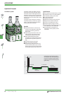
The frequency inverter FR-F 740 provides a
large number of protective functions that
protect the drive and the inverter against
damage in case of any malfunction.
If an error occurs, the output of the inverter
is suspended and the control panel
returns an error message.
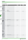
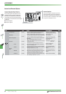
Protective Functions Overview
HOLD
ቢ
Operation panel lock Operation lock mode ist set.
Press and hold the MODE key for 2 s to enable
the operation panel.
Er1
ቢ
Write disable error
This error occurs when a write operation is attempted with Pr.77 = 1,the frequency jump ranges
overlap,the ranges for the flexible 5-point V/f characteristic overlap or no communication is possi
-
ble between the control panel and the frequency inverter.
Check the setting of Pr.77,Pr.31 to 36 Pr.100 to
109 and the connection of the operation panel
and inverter.
Er2
ቢ
Write error
This error occurs when a write operation is attempted with the inverter in operation when the value
of Pr.77 <> 2 and an STF or STR start signal is active.
Check the setting of Pr.77.The frequency
inverter must be in stop mode.
Er3
ቢ
Calibration error Analog input bias and gain calibration values are too close. Check the parameter C3,C4,C6 and C7
Er4
ቢ
Mode designation error This error occurs when you try to set a parameter in NET mode when PR.77 <> 2.
Check the setting of Pr.77. Set the operating
mode to operation via control panel.
rE1
ቢ
Parameter read error An error occurred in the E²PROM on the operation panel side during parameter copy reading.
Repeat the copy operation.Check the control
panel connections.Please contact your nearest
MITSUBISHI ELECTRIC representative if the error
occurs repeatedly.
rE2
ቢ
Parameter write error An error occurred in the E²PROM on the operation panel side during parameter copy writing.
Repeat the copy operation with the inverter
stopped.Check the control panel connections.
Please contact your nearest MITSUBISHI ELEC-
TRIC representative if the error occurs repeat-
edly.
rE3
ቢ
Parameter verification
error
Data on the operation panel side and inverter side are different.An error occurred in the E²PROM on
the operation panel side during parameter verification.
Press the SET key to continue verification.Check
the control panel connections.Please contact
your nearest MITSUBISHI ELECTRIC representa-
tive if the error occurs repeatedly.
rE4
ቢ
Model error A different model was used for parameter write and verification during parameter copy.
Use the same model for parameter copy and
verification.
Err.
Error
The RESET signal is active or there is an error in the communication between the frequency inverter
and the control panel.
Deactivated the RESET signal.Check the con
-
nections between the control panel and the
frequency inverter.
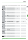
OL
Overcurrent during
acceleration
If a current of more than 110%
ባ
of the rated inverter current flows in the motor,this function
stops the increase in frequency until the overload current reduces to prevent the inverter from re
-
sulting in overcurrent shut-off.When the overload current has reduced below 110%,this function
increases the frequency again.
Increase the stall prevention operation level
with Pr.22 "stall prevention operation level"
or disable stall prevention with Pr.156 "stall
prevention operation selection".
Overcurrent during con
-
stant speed operation
If a current of more than 110%
ባ
of the rated inverter current flows in the motor,this function low
-
ers the frequency until the overload current reduces to prevent overcurrent shut-off.When the over
-
load current has reduced below 110%,this function increases the frequency up to the set value.
Overcurrent during
deceleration
If a current of more than 110%
ባ
of the rated inverter current flows in the motor,this function
stops the decrease in frequency until the overload current reduces to prevent theinverter from re
-
sulting in overcurrent shut-off.When the overload current has reduced below 110%,this function
decreases the frequency again.
oL
Overvoltage during
deceleration
If the regenerative energy of the motor increases too much to exceed the brake capability,this func
-
tion stops the decrease in frequency to prevent overvoltage shut-off.As soon as the regenerative
energy has reduced,deceleration resumes.
Increase the deceleration time with Pr.8 "decel
-
eration time".
rb
Regenerative brake
prealarm
Too much energy is being fed into the brake resistor (model 01800 and above).
Increase the deceleration time.Check the Pr.30
and 70 values.
PS
Inverter was stopped via
control panel
STOP key on the control panel was pressed during external operating mode. Check the parameter 77.
TH
Electronic thermal relay
function prealarm
The prealarm of the electronic motor protection switch has activated. The load or number of work cycles is too high.
MT
ቢ
Maintenance signal
output
The cumulated operating time has reached the preset value.
The value in Pr.503 is larger than the setting of
Pr.504.
CP
Parameter copy
Attempt to perform a copy operation from a frequency inverter model 01160 or lower to a model
01800 or higher.
Reset parameters 9,30,51,52,54,56 57,61,70,
72,80,90,158,190-196 and 893.
FN
Fan fault The cooling fan is not operating as set in Pr.244. Replace the cooling fan.
PROTECTIVE FUNCTIONS