


12
MITSUBISHI ELECTRIC
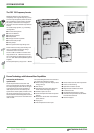
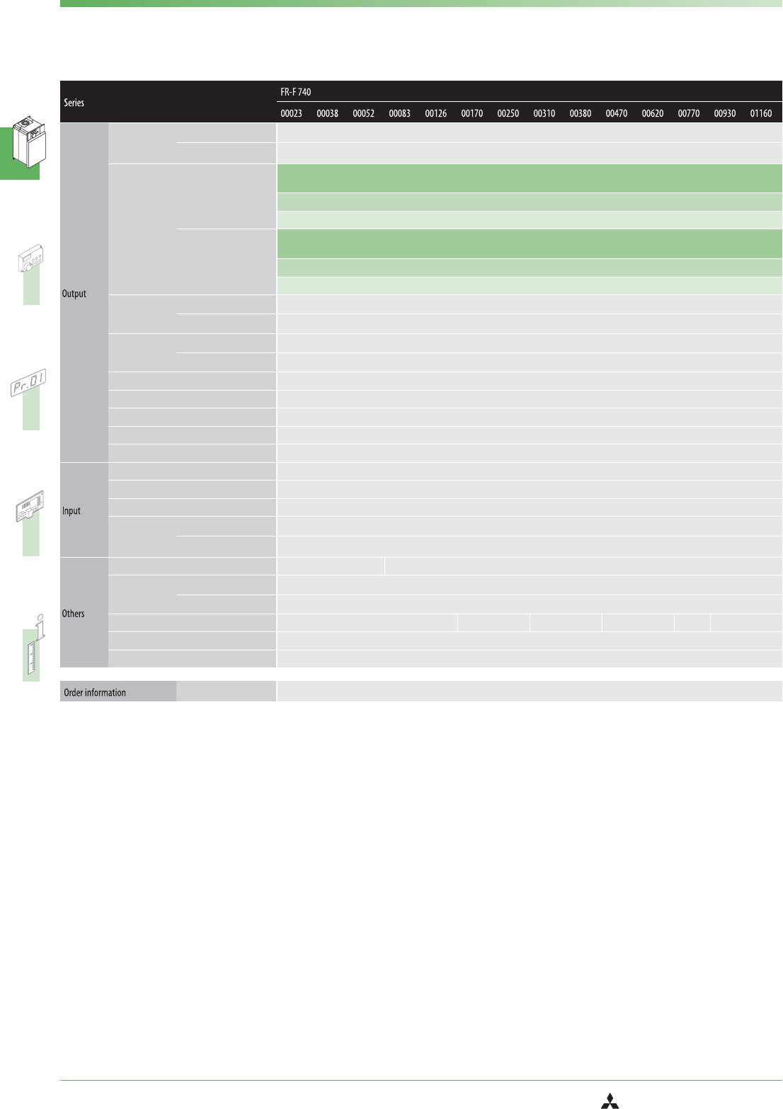
FR-F 740 EC/E1
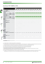
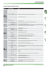
Specifications FR-F 740-00023 to -01160
Rated motor
capacity
ᕃ
[kW]
120% overlaod capacity
ቦ
0.75 1.5 2.2 3.7 5.5 7.5 11 15 18.5 22 30 37 45 55
150% overlaod capacity
0.75 1.5 2.2 3.7 5.5 7.5 11 15 18.5 22 30 37 45 55
Rated
current
[A]
ቧ
120%
overlaod
capacity
ቦ
2.3
(2.0)
3.8
(3.2)
5.2
(4.4)
8.3
(7.1)
12.6
(10.7)
17
(14.5)
25
(21.3)
31
(26.4)
38
(32.3)
47
(40.0)
62
(52.7)
77
(65.5)
93
(79.1)
116
(98.6)
2.5 4.2 5.7 9.1 13.9 18.7 27.5 34.1 41.8 51.7 68.2 84.7 102.3 127.5
2.8 4.6 6.2 10 15.1 20.4 30 37.2 45.6 56.4 74.4 92.4 111.6 139.2
150%
overlaod
capacity
2.1
(1.8)
3.5
(3.0)
4.8
(4.1)
7.6
(6.4)
11.5
(9.8)
16
(13)
23
(19)
29
(24)
35
(30)
43
(36)
57
(48)
70
(60)
85
(72)
106
(90)
2.5 4.2 5.8 9.1 13.8 19.2 27.6 34.8 42 51.6 68.4 84 102 127.2
3.1 5.2 7.2 11.4 17.2 24 34.5 43.5 52.5 64.5 85.5 105 127.5 159
Output capacity
[kVA]
120% overlaod capacity
ቦ
1.8 2.9 4.0 6.3 9.6 13 19.1 23.6 29.0 35.8 47.3 58.7 70.9 88.4
150% overlaod capacity
1.6 2.7 3.7 5.8 8.8 12.2 17.5 22.1 26.7 32.8 43.4 53.3 64.8 80.8
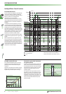
Overload current
rating
ᕄ
120% overlaod capacity
120% of rated motor capacity for 3s;110% for 1 min.(max.ambient temperature 40°C) – typical for pumps and fans
150% overlaod capacity
150% of rated motor capacity for 3s;120% for 1 min.(max.ambient temperature 50°C) – typical for conveyor belts and centrifuges
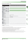
Voltage
ᕅ
3-phase AC,0 V to power supply voltage
Frequency range 0.5–400 Hz
Control method V/f control,optimum excitation control or simple magnetic flux vector control
Modulation control Sine evaluated PWM,Soft PWM
Carrier frequency 0.7 kHz–14.5 kHz (user adjustable)
Power supply voltage 3-phase,380–480 V AC,−15% / +10%
Voltage range 323–528 V AC at 50 / 60 Hz
Power supply frequency 50 / 60 Hz ±5%
Rated input
capacity
ᕆ
[kVA]
120% overlaod capacity
ቦ
2.8 5.0 6.1 10 13 19 22 31 37 45 57 73 88 110
150% overlaod capacity
2.54.55.59 121720283441526680100
Cooling Self cooling Fan cooling
Power loss
[kW]
120% overlaod capacity
ቦ
0.06 0.08 0.1 0.16 0.19 0.24 0.34 0.39 0.49 0.58 0.81 1.0 1.17 1.51
150% overlaod capacity
0.05 0.08 0.09 0.14 0.18 0.22 0.31 0.35 0.44 0.52 0.71 0.93 1.03 1.32
Frame size C D E F G H
Inverter weight [kg] 3.5 3.5 3.5 3.5 3.5 6.5 6.5 7.5 7.5 13 13 23 35 35
Reactor weight [kg] ––––––––––––––
ቩ
Order no.
156569 156570 156571 156572 156573 156594 156595 156596 156597 156598 156599 156600 156601 156602
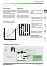
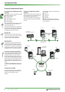
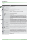
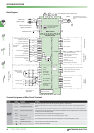
SYSTEM DESCRIPTION
ቢ
The performance figures at the rated motor capacity are based on a motor voltage of 400 V.
ባ
The overload capacity in % is the ratio of the overload current to the inverter’s rated current in the respectiveoperating mode. For repeated duty cycles allow sufficient time for the inverter and the motor to
cool below the temperature reached at 100% load. The waiting periods can becalculated using the r.m.s. current method (I² ×t), for which knowledge of the duty.
ቤ
The maximum output voltage cannot exceed the power supply voltage. The output voltage can be varied overthe entire power supply voltage range.
ብ
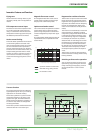
The rated input capacity varies depending on the impedance values on the power supply side of theinverter (including the cables and input reactor).
ቦ
When the load curve with 120% overload capacity is selected the maximum permitted ambient temperature is 40°C.
ቧ
When operating with carrier frequencies ≥3 kHz this value is reduced automatically as soon as the frequency inverter exceeds the rated output current shown in parentheses (= 85% load).
ቨ
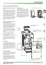
When the cable bushing for the optional expansion cards is broken out the unit has anIP 00 protection rating.
ቩ
The suffix EC or E1 in the model designation identifies the CE versions of the frequency inverter (for the European Union). The inverter types FR-F740-02160 and above are all delivered in the E1 versionas
standard (PCBs with two coats of protective varnish). The EC version (varnished PCBs) is standard for types FR-F740 00023 through 01800. The otherversion as always available as an option.
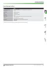
I
rated
ቧ
I
max.60 s
I
max.3 s
I
rated
ቧ
I
max.60 s
I
max.3 s