


25
MITSUBISHI ELECTRIC
FR-F 740 EC/E1
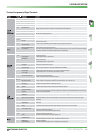
184
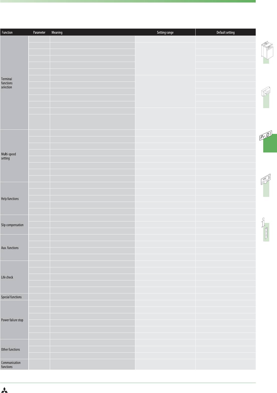
AU terminal function selection
0–8 / 10–14 / 16 / 24 / 25 / 37 / 62–67 /9999 4
185
JOG terminal function selection
0–8 / 10–14 / 16 / 24 / 25 /
37 / 62 / 64–67 / 9999
5
186
CS terminal function selection
6
187
MRS terminal function selection
24
188
STOP terminal function selection
25
189
RES terminal function selection
62
190
RUN terminal function selection
0–5 / 7 / 8 / 10–19 / 25 / 26 / 45–47/ 64 /
70–78 / 90–96 / 98 / 99 / 100–105 / 107 /
108 / 110–116 / 125 / 126 / 145–147 /
164 / 170 / 190–196 / 198 / 199 / 9999
ቧ
0
191
SU terminal function selection
1
192
IPF terminal function selection
2
193
OL terminal function selection
3
194
FU terminal function selection
4
195
ABC1 terminal function selection
0–5 / 7 / 8 / 10–19 / 25 / 26 / 45–47/ 64 /
70–78 / 90 / 91 / 94–96 / 98 / 99 / 100–105 /
107 / 108 / 110–116 / 125 / 126 / 145–147 /
164 / 170 / 190 / 191 / 194–196 /
198 / 199 / 9999
ቧ
99
196
ABC2 terminal function selection
9999
232
Multi-speed setting (speed 8)
ቢ
0–400 Hz / 9999 9999
233
Multi-speed setting (speed 9)
ቢ
0–400 Hz / 9999 9999
234
Multi-speed setting (speed 10)
ቢ
0–400 Hz / 9999 9999
235
Multi-speed setting (speed 11)
ቢ
0–400 Hz / 9999 9999
236
Multi-speed setting (speed 12)
ቢ
0–400 Hz / 9999 9999
237
Multi-speed setting (speed 13)
ቢ
0–400 Hz / 9999 9999
238
Multi-speed setting (speed 14)
ቢ
0–400 Hz / 9999 9999
239
Multi-speed setting (speed 15)
ቢ
0–400 Hz / 9999 9999
240
Soft-PWM operation selection
ቢ
0/1 1
241
Analog input display unit switchover
ቢ
0/1 0
242
Terminal 1 added compensation amount (terminal 2)
0–100% 100%
243
Terminal 1 added compensation amount (terminal 4)
0–100% 75%
244
Cooling fan operation selection
0/1 0
245
Rated slip
0–50% / 9999 9999
246
Slip compensation time constant
0,01–10 s 0.5 s
247
Constant-output region slip compensation selection
0 / 9999 9999
250
Stop selection
0–100 s / 1000–1100 s / 8888 / 9999 9999
251
Output phase failure protection selection
0/1 1
252
Override bias
0–200% 50%
253
Override gain
0–200% 150%
255
Life alarm status display
(0–15) 0
256
Inrush current suppression circuit life display
(0–100%) 100%
257
Control circuit capacitor life display
(0–100%) 100%
258
Main circuit capacitor life display
(0–100%) 100%
259
Main circuit capacitor life measuring
0/1 0
260
PWM frequency automatic switchover
0/1 1
261
Power failure stop selection
0/1/2 0
262
Subtracted frequency at deceleration start
0–20 Hz 3 Hz
263
Subtraction starting frequency
0–120 Hz / 9999 50 Hz
264
Power-failure deceleration time 1
0–360 s / 0–3600 s 5s
265
Power-failure deceleration time 2
0–360 s / 0–3600 s / 9999 9999
266
Power failure deceleration time switchover frequency
0–400 Hz 50 Hz
267
Terminal 4 input selection
0/1/2 0
268
Monitor decimal digits selection
ቢ
0 / 1 / 9999 9999
269
Parameter for manufacturer setting. Do not make setting!
——
331
RS-485 communication station
0–31
(0–247)
0
PARAMETER