


20
MITSUBISHI ELECTRIC
FR-F 740 EC/E1
CONTROL PANELS
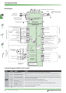
The inverter can alternatively be operated
via external signals or directly via the ope
-
ration panel FR-DU07 or the control panels
FR-PU04.
On the FR-DU07 control panel the opera
-
ting mode is selected by pressing the
PU/EXT key. On the FR-PU04 the EXT key
selects operation by external signals and
the PU key selects operation via the control
panel.
Operating Modes
U
V
W
FR-F740EC
STR
STF
PC
10
2
5
R1
S1
S2
I
I
I
L1
L2
L3
L1
L2
L3
Q1
Motor
Mains
Start
Frequency
setting
Sampleconnection
These connections
are required for
combined
operation or
operation by
external signals.
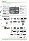
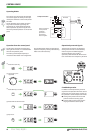
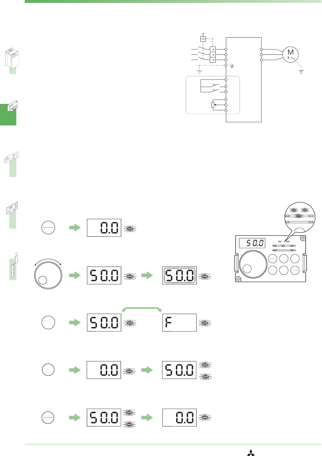
Operation from the controlpanel
The direction of rotation and frequency
setting of the inverter are controlled from
the built-in operation panel.
The setting of the output frequency is
increased or decreased via the Digital Dial.
The example below shows the operational
steps for a frequency setting with following
motor start and motor stop.
PU
EXT
+-
SET
PU
FWD
FWD
STOP
RESET
FWD
PU
PU
PU
PU
PU
PU
PU
PU
ቢ
Press the PU/EXT key
ባ
Set frequency with
Digital Dial
ቤ
Press SET key to confirm
ቦ
Stop motor
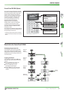
Operation by external signals
The direction of rotation and frequency
setting of the inverter are controlled by
external signals. The following figure
shows the display on the built-in
operation panel FR-DU07 for forward rota
-
tion of the motor and a frequency of 50 Hz.
Combined operation
In addition to the operation by external
signals and the operation from the control
panel (built-in or external) the inverter can
be operated in combined operation mode.
Ȝ
Setting value preset from the control
panel and external starting signal.
Ȝ
External setting value signal and star
-
ting signal from the control panel.
ብ
Press FWD to start the motor
Hz
MON
PU
REV
REV
SET
EXT
PU
EXT
STOP
RESET
NET
FWD
FWD
MODE
P. RU N
FR-DU07
A
V
MON
PU
REV
REV
EXT
U
NET
FWD
FW
P.R UN