


14
MITSUBISHI ELECTRIC
FR-F 740 EC/E1
Specifications
SYSTEM DESCRIPTION
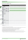
Frequency
setting
resolution
Analog input
0.015 Hz / 0–50 Hz (terminal 2,4:0–10 V / 12 bit)
0.03 Hz / 0–50 Hz / (terminal 2,4:0–5 V / 11 bit,0–20 mA / 11 bit,terminal 1:−10–+10 V / 11 bit)
0.06 Hz / 0–50 Hz (terminal 1:0–±5 V / 10 bit)
Digital input
0.01 Hz
Frequency accuracy
±0.2% of the maximum output frequency (temperature range 25° ± 10°C) via analog input;
±0.01% of the set output frequency (via digital input)
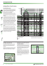
Voltage / frequency characteristics
Base frequency adjustable from 0 to 400 Hz;
selection between constant torque,variable torque or optional flexible 5-point V/f characteristics
Starting torque 120% (3 Hz) when set to simple magnetic flux vector control and slip compensation
Acceleration / deceleration time 0;0.1 to 3600 s (can be set individually)
Acceleration / deceleration characteristics Linear or S-form course,user selectable
DC injection brake
Operating frequency (0–120 Hz),operating time ( 0–10 s) and operating voltage (0–30%) can be set individually.
The DC brake can also be activated via the digital input.
Stall prevention Respones threshold 0–150%,user adjustable,also via analog input
Motor protection Electronic motor protection relay (rated current user adjustable)
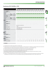
Frequency
setting values
Analog input
Terminal 2,4:0–5 V DC,0–10 V DC,0/4–20 mA
Terminal 1:0–±5 V DC,0–±10 V DC
Digital input
Operation panel or optional expansion board
Start signal Available individually for forward rotation and reverse rotation.Start signal automatic self-holding input (3-wire input) can be selected.
Input signals
Any of 12 signals can be selected using parameters 178 to 189 (input terminal function selection):
multi speed,second parameter function,terminal 4 input,JOGoperation,automatic restart after instantaneous power failure,external thermal relay
input,FR-HC connection (inverter operation enable signal) and FR-HC connection (instantaneous power failure detection),control panel operation/ex
-
ternal interlock signal,PIDcontrol,control panel operation,control panel<->external operation,output stop,start self-holding,forward/reverse rota
-
tion command,inverter reset,PTC thermistor input,PID forward/reverse operation switchover,control panel<->NET,NET<->external operation,
command source switchover
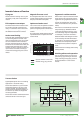
Output
signals
Operating state
Any of 7 signals can be selected using parameter 190 to 196 (output terminal function selection):
Frequency control status,instantaneous power failure (under voltage),overload warning,output frequency detection,second output frequency
detection,regenerative brake with pre-alarm (01800 and above), electronic thermal relay function with pre-alarm,control panel operation
mode,inverter operation ready,output current detection,zero current detection,PID lower limit,PID upper limit,PID forward rotation/reverse ro-
tation,commercial power supply-inverter switchover,direct mains operation motor 1-4,frequency inverter operation motor 1-4,inverter running
start command ON,deceleration at an instantaneous power failure,PID control activated,re-start,PID output suspension,life time alarm,alarm
output 3 (OFF signal),power savings average value update timing,current average monitor,alarm output2,maintenance timer alarm,remote
outputs,minor failure output,alarm output,traverse operation,open-collector outputs (5 outputs),relay outputs (2 outputs),alarm code outputs
(4 bits via open-collector)
When using the
FR-A7AY option
In addition to the above operating modes parameters 313-319 (function selection for the additional 7 output terminals) can also be used to as-
sign the following four signals:control circuit capacitor life,main circuit capacitor life,cooling fan life,inrush current limit circuit life
Pulse/analog output
You can also use parameter 54 (assign analog current output) and 158 (assign analog voltage output) to assign the following displays to one or
both outputs:
output frequnecy,motor current (steady or peak),output voltage,frequency setting value,motor running speed,converter output voltage (steady
or peak),electronic thermal relay function load factor,input voltage,output voltage,load meter, reference voltage output,motor load factor,en
-
ergy saving effect,regenerative brake circuit duty (01800 and above),PID set point,PID process value
Control unit
display
(FR-PU04/
FR-DU07)
Operating state
Output frequency,motor current (steady or peak value),output voltage,alarm indication,frequency setting,motor running speed, converter out
-
put voltage (steady or peak value),electronic thermal load factor,input power,output power,road meter,cumulative energization time,actual
operation time,motor load factor, watt-hours meter,power saving effect,cumulative saving power,regenerative brake circuit duty (01800 and
above),PID set point,PID process value,PID deviation monitor,I/O terminal monitor, optional input terminal monitor (FR-DU07 only),optional
output terminal monitor (FR-DU07 only),option fitting state monitor (FR-PU04 only), terminal assignment state (FR-PU04 only)
Alarm definition
Alarm definition is displayed when the protective function is activated,the output voltage/current/frequency/cumulative energization time right
before the protection function was activated and the past 8 alarm definitions are stored.
Interactive guidance Operation guide/trouble shooting with a help function (FR-PU04 only)
Protective
functions
Overcurrent cutoff (during acceleration,deceleration or at constant speed),overvoltage cutoff (during acceleration,deceleration or at constant
speed),inverter protection thermal operation,motor protection thermal operation,heatsink overheat,instantaneous power failure occurence,
under voltage,input phase failure,motor overload,output short circuit,ground fault overcurrent,output phase failure,external thermal relay
operation,PTC thermistor operation,option alarm,parameter error,control unit disconnection,retry count excess,CPU alarm,power supply short
for control panel,24 V DC power output short,output current detection value over,inrush resitance overheat,communication error (frequency
inverter),analog input alarm,internal circuit alarm (15 V DC power supply),fan fault,overcurrent stall prevention,overvoltage stall prevention,
electronic thermal pre-alarm,control unit stop,maintenance timer alarm (FR-DU07 only),MT-BU5 external brake module overload (01800 and
above),parameter write error,copy error,operation panel lock,parameter copy error
Protection rating*
IP20 (FR-F 740-00023 to -00620);
IP00 (FR-F 740-00770 to -12120)
Ã
FR-DU07: IP40 (does not apply for the PU connection)