


31
MITSUBISHI ELECTRIC
FR-F 740 EC/E1
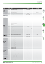
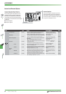
When a protective function is activated,
the output of the inverter is switched off.
The motor coasts to a halt. The output
remains switched off until the error cause
is eliminated and the inverter reset.
The inverter can be reset following four
different methods:
Ȝ
Switch the power supply OFF and ON
again.
Ȝ
Switch the reset signal ON for at least
0.1 s.
Ȝ
Press the RESET key on the control
panel.
Ȝ
Use the automatic restart function (Pr.
65, Pr. 67-69)
If the reset signal is ON continuously, the
operation panel FR-DU07 returns an error
message while the control unit FR-PU04
indicates that the reset procedure is in
progress.
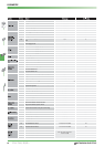
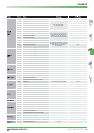
When a protective function is activated,
the operation panel FR-DU07 returns an er
-
ror code as listed in the table above.
The control panel FR-PU04 returns error
messages in clear.
If on occurrence of an error the input
protection contactor is toggled the error
message cannot be retained, since there is
no power supply for the control circuit.
If the error message is intended to be
retained in spite of an activation of the pro
-
tectve contactor, the control circuit has to
be supplied by a separate power supply.
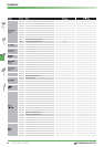
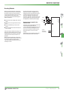
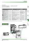
Separate power supply for the
control circuit
The figure on the right shows the connecti
-
on of the separate 380-480 V AC
(-15%/+10%) power supply for the control
circuit. The current consumption is 2 A.
Prior to the connection remove the two
short bars upon L11 and L21 on the
inverter.
Please refer to the according manual for a
precise description of the connection.
Resetting Methods
U
V
W
FR-F700
L11
L21
I
I
I
L1
L2
L3
L1
L2
L3
Q1
Mains
Separate
mains supply
of control circuit
PROTECTIVE FUNCTIONS