


11
MITSUBISHI ELECTRIC
FR-F 740 EC/E1
Hz
MON
PU
REV
REV
SET
EXT
PU
EXT
STOP
RESET
NET
FWD
FWD
MODE
P. RU N
FR-DU07
A
V
8888
Long Service Life and Easy Maintenance
New components for longer service
life
The components of this new generation of
frequency inverters are specified for a ser
-
vice life of 10 years (mean annual ambient
temperature 40°C, 80% load in an environ
-
ment free of aggressive gases, flammable
gases, oil mist, dust and dirt). Among other
things,thisismadepossiblebythe
newly-developed, long-life cooling fans
that are monitored by the inverter. The life
of the cooling fans can also be made signi
-
ficantly longer by using Parameter 244,
which controls the selective shutdown
feature.
Modern diagnostics functions furt
-
her extend service life
The ageing of the main circuit capacitors,
the control circuit power capacitor, the in
-
ternal cooling fans and the inrush current
limiter circuit can be checked with the mo
-
nitoring functions. If the inrush resistor
overheats an alarm is displayed.
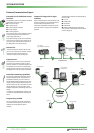
The alarms for the main circuit capacitors,
control circuit capacitor, inrush current li-
miter and internal fans can all be output to
a network or via the optional FR-A7AY
module.
This makes it possible to prevent mal-
functions by configuring diagnostics
alarms to be triggered when the end of the
service life is reached.
The inverter also has an internal program
that can evaluate the ageing of the main
circuit capacitors. This feature is only avai
-
lable when a motor is connected to the
inverter.
Service timer
The frequency inverters of this series all
have an integrated service timer that auto
-
matically triggers an alarm after a set num
-
ber of operating hours. This feature can be
used for monitoring the frequency inverter
itself or a peripheral component. The valu
-
es of the mean output current and the ser
-
vice timer can also be output as analog
signals.
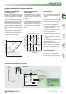
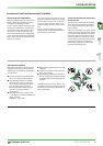
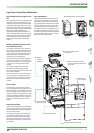
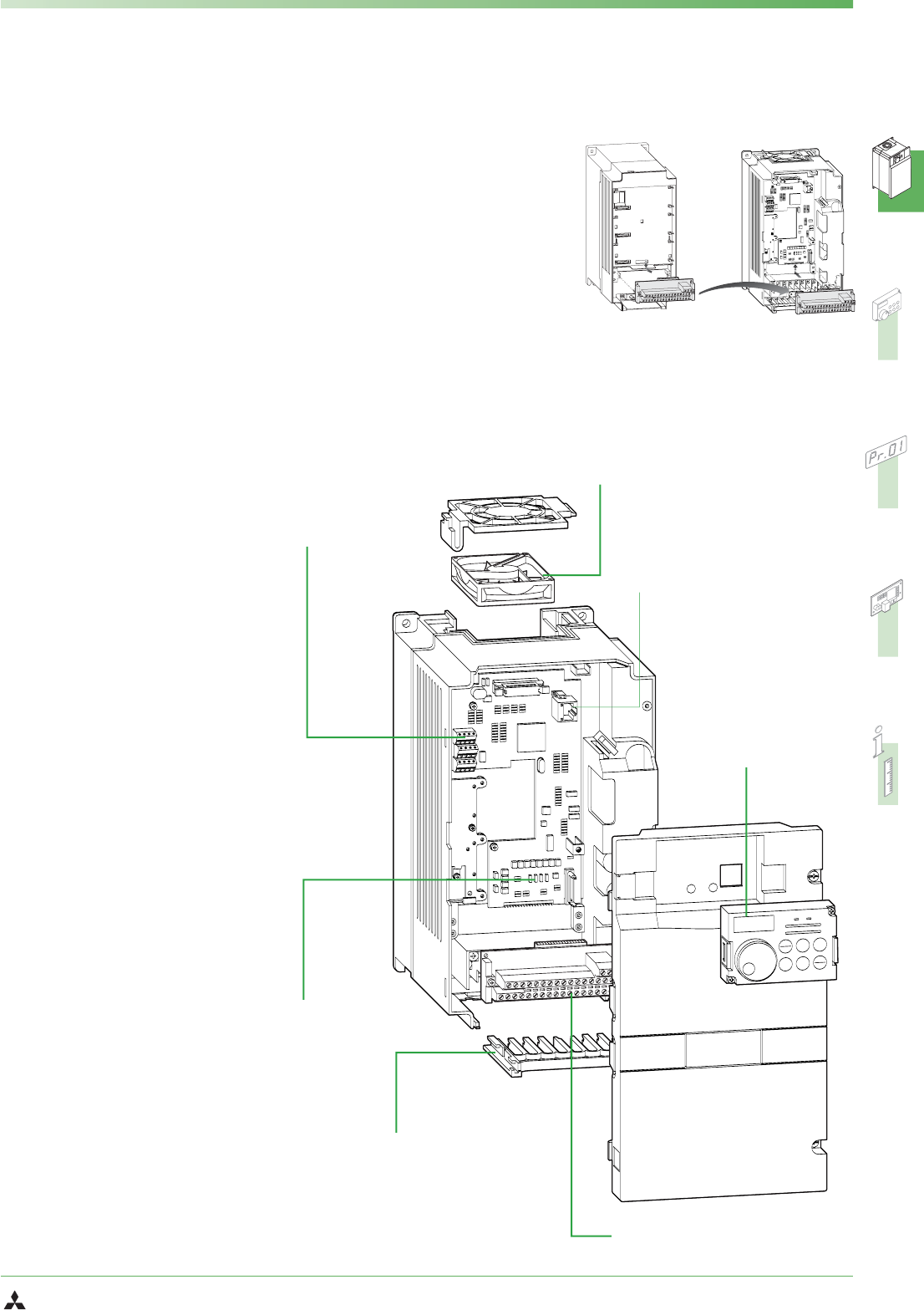
Improved handling
The main cooling fan is easily accessible at
the top of the inverter unit, allowing quick
and easy replacement without removal of
the connection cables.
The cable guide comb (see illustration) is
removable and makes routing the cables
quick and trouble-free. After the cables
have been connected the cover can then
be replaced (for frequency inverters up to
type 00620).
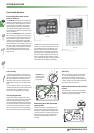
Easy replacement
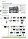
The terminal block for the control circuit
connections is removable to enable easy
replacement of the inverter unit for servi
-
cing, which greatly facilitates both installa
-
tion and maintenance work. You can also
use the removable terminal block of the
FR-F500 series, which is compatible to the
FR-F700 series. However, please note that
some of the functions of the FR-F700 series
are not available when you use a terminal
block from the FR-F500 series.
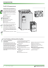
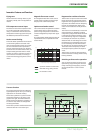
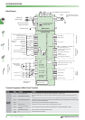
Ȝ
RS-485
interface
terminals
Ȝ
Easy replacement of the
fan cassette
Ȝ
RJ45 connector for control
panel and RS-485 communica-
tions port
Ȝ
Removable
control panel
Ȝ
Removable terminal block
Ȝ
Cable guide comb
Ȝ
Slot for optional
expansion cards
Replacement of the terminal block:
FR-F500
FR-F700
SYSTEM DESCRIPTION