


16
MITSUBISHI ELECTRIC
FR-F 740 EC/E1
SYSTEM DESCRIPTION
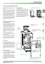
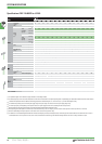
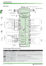
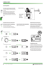
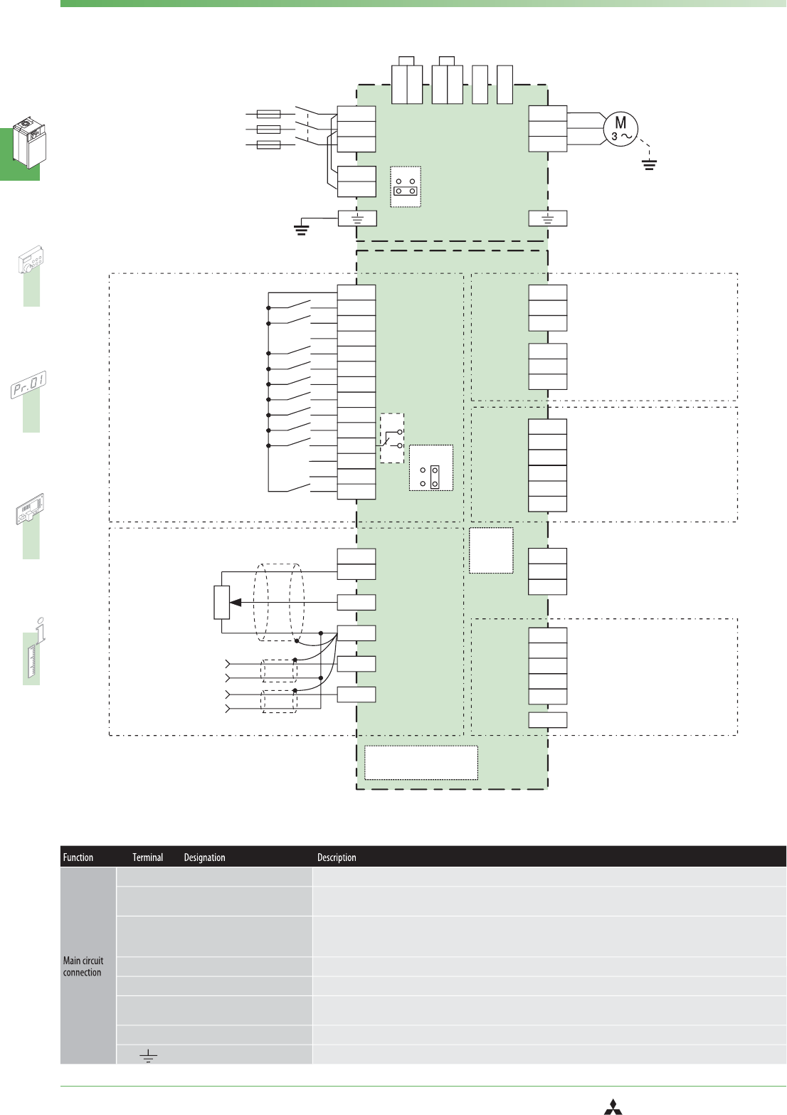
Terminal Assignment of Main Circuit Terminals
PC
STOP
STF
STR
RH
RM
RL
RT
PCT
CS
RES
RUN
TXD+
SU
TXD-
OL
IPF
RXD+
FU
RXD-
SE
SG
VCC
CA
AM
5
10
10E
0–5 V DC
4–20 mA DC
+10 V
+5 V
(0–10 VDC
4–20 mADC)*
(0–5 VDC
0–10 VDC)*
2
5
1
4
SD
L1
A2
A1
B2
B1
C2
C1
L11
L2
L21
L3
U
V
W
PX
PR
N/-
CN8*
P/+
P1
(+)
(+)
(-)
(-)
OFF
ON
JOG
MRS
AU
AU
SOURCE
SINK
0– 10 V DC±
(0– 5 V DC)*±
PTC
L1, L2, L3
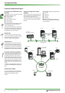
Mains supply connection Mains power supply of the inverters (380–480 V AC,50/60 Hz);(380-500 V – 01800 and above)
P/+, N/−
External brake unit connection
An optional external brake resistor can be connected to the terminals P and N or you can connect a optional high power factor con
-
verter.
P1, P/+
Converter choke coil connection
An optional choke coil can be connected to the terminals P1 and P/+.The jumper on terminals P1 and P/+ must be removed when
this optional choke coil is used on frequency inverter models 01160 and below.The DC reactor supplied with the unit must be installed
on frequency inverter models 01800 and above.
PR, PX
Please do not remove or use terminals PR and PX or the jumper connected.
U, V, W
Motor connection Voltage output of the inverter (3-phase,0 V up to power supply voltage,0,5–400 Hz)
L11, L21
Control circuit mains supply
connection
To use external power for the control circuit connect the mains power to L11/L21 (and remove jumpers L1 and L2).
CN8
Ext.brake transistor control Control connection for the MT-BU5 external brake module
PE Protective earth connection of inverter
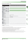
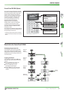
Block Diagram
Relay output 1
(Alarm output)
Relay output 2
Relay outputs
Open collector
outputs
Motor
Intermediate circuit connections
3phase AC
power supply
Control circuit mains
supply connection
Protective earth
Control input signals
Frequency setting
inputs
RS-485
terminal
Main circuit
Control circuit
Running (Motor operation)
frequency setting value/current
value comparison
Instantaneous power failure
Overload
Frequency detection
Power supply for OC outputs
Data transmission
Data reception
GND (Ground)
5 V (max. 100 mA)
Analog signal output (0 –10 V DC / 1 mA)
Analog signal output (0/4 –20 mA)
Analog output common
24 V DC Output (max. 100 mA)
Forward rotation start
Reverse rotation start
Start self-retaining selection
High speed
Middle speed
Low speed
Second function selection
Jog mode
Output stop
Current input selection / PTC
Selection of automatic restart
Common
Reset
Multi-speed
selection
Frequency setting
potentiometer
0,5W1kΩ
Auxiliary input
Current input
Jumper for activating the
integrated interference
suppression filter
Connector/Slot for plug-in
option connection
PU Con-
nector
*
Input area can be set
via parameters.
*The CN8 connector is provi
-
ded with the inverter 01800 or
more.