


10.7
Section 10
Inspection and Reconditioning
10
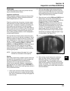
Valve Guides
If a valve guide is worn beyond specifications, it will not
guide the valve in a straight line. This may result in
burnt valve faces or seats, loss of compression, and
excessive oil consumption.
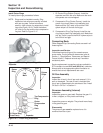
To check valve guide-to-valve stem clearance,
thoroughly clean the valve guide and, using a split-ball
gauge, measure the inside diameter. Then, using an
outside micrometer, measure the diameter of the valve
stem at several points on the stem where it moves in
the valve guide. Use the largest stem diameter to
calculate the clearance. If the intake clearance
exceeds 0.038/0.076 mm (0.0015/0.003 in.) or the
exhaust clearance exceeds 0.050/0.088 mm
(0.0020/0.0035 in.), determine whether the valve stem
or guide is responsible for the excessive clearance.
Maximum (I.D.) wear on the intake valve guide is
7.134 mm (0.2809 in.) while 7.159 mm (0.2819 in.)
is the maximum allowed on the exhaust guide. The
guides are not removable but can be reamed 0.25 mm
(0.010 in.) oversize with Tool No. KO1026. Valves with
0.25 mm oversize stems must then be used.
If the guides are within limits but the valve stems are
worn beyond limits, replace with new valves.
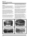
Valve Seat Inserts
Hardened steel alloy intake and exhaust valve seat
inserts are press fitted into the cylinder head. The
inserts are not replaceable on the engines but can be
reconditioned if not too badly pitted or distorted. If
cracked or badly warped, the cylinder head should be
replaced.
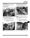
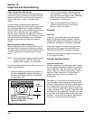
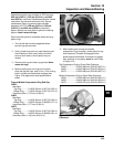
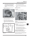
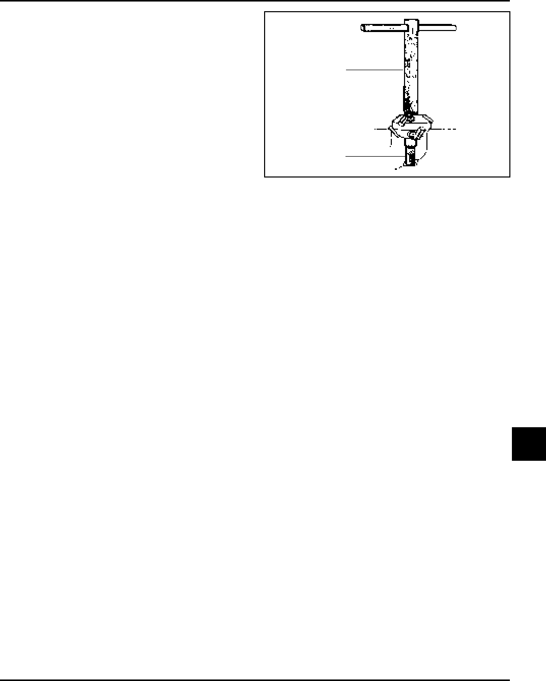
Recondition the valve seat inserts following the
instructions provided with the valve seat cutter being
used. A typical cutter is shown in Figure 10-6. The final
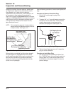
cut should be made with an 89° cutter as specified for
the valve seat angle in Figure 10-5. With the proper
45° valve face angle as specified in Figure 10-5 and
the valve seat cut properly (44.5° as measured from
centerline when cut 89°) this would result in the
desired 0.5° (1.0° full cut) interference angle where the
maximum pressure occurs on the outside diameters of
valve face and seat.
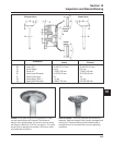
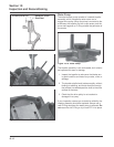
Figure 10-6. Typical Valve Seat Cutter.
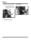
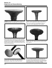
Lapping Valves
Reground or new valves must be lapped in, to provide
fit. Use a hand valve grinder with suction cup for final
lapping. Lightly coat valve face with “fine” grade of
grinding compound, then rotate valve on seat with
grinder. Continue grinding until smooth surface is
obtained on seat and on valve face. Thoroughly clean
cylinder head in soap and hot water to remove all
traces of grinding compound. After drying cylinder
head, apply a light coating of SAE 10 oil to prevent
rusting.
Intake Valve Stem Seal
These engines use valve stem seals on the intake
valves. Always use a new seal when valves are
removed from cylinder head. The seals should also be
replaced if deteriorated or damaged in any way. Never
reuse an old seal.
Valve Seat
Cutter
Pilot