


6.4
Section 6
Lubrication System
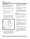
To install the switch, follow these steps:
1. Apply Loctite
®
No. 592 Pipe Sealant with
Teflon
®
(or equivalent) to the threads of the
switch.
2. Install the switch into the tapped hole in the
breather cover. See Figure 6-5.
3. Torque the switch to 4.5 N·m (40 in. lb.).
Testing
Compressed air, a pressure regulator, pressure gauge
and a continuity tester are required to test the switch.
1. Connect the continuity tester to the blade terminal
and the metal case of the switch. With 0 psig
pressure applied to the switch, the tester should
indicate continuity (switch closed).
2. Gradually increase the pressure to the switch. As
pressure increases through the range of 3.0/5.0
psig, the tester should indicate a change to no
continuity (switch open). The switch should
remain open as the pressure is increased to
90 psig maximum.
3. Gradually decrease the pressure through the
range of 3.0/5.0 psig. The tester should indicate a
change to continuity (switch closed) down to 0
psig.
4. Replace the switch if it does not operate as
specified.
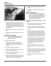
Crankcase Breather System
The crankcase breather system is a necessary
complement to the lubrication system. To help prevent
the engine oil from weeping out past shafts, seals, and
gaskets during operation, it is desirable to have a low
vacuum inside the crankcase. A typical crankcase
breather system incorporates a simple one-way valve
to provide the desired vacuum.
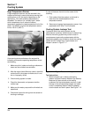
Breather Design and Function
The breather system on these engines is designed to
serve two functions; prevent excess oil from
accumulating in the rocker arm chambers, and
maintain the desired vacuum in the crankcase. The
system utilizes a spring steel reed and stop mounted in
each bank of the crankcase, between the lifter bores.
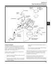
See Figure 6-6.
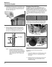
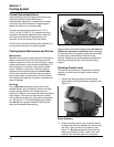
Figure 6-6. Reed/Breather Assembly in Crankcase.
When the pistons move downward, crankcase air is
pushed past the reeds into the cylinder head cavities.
On the #2 cylinder, the upper end of the head is
completely sealed by the valve cover, so a low, positive
pressure is created in the head cavity. The valve cover
on the #1 cylinder has an integral breather assembly to
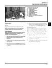
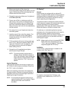
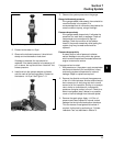
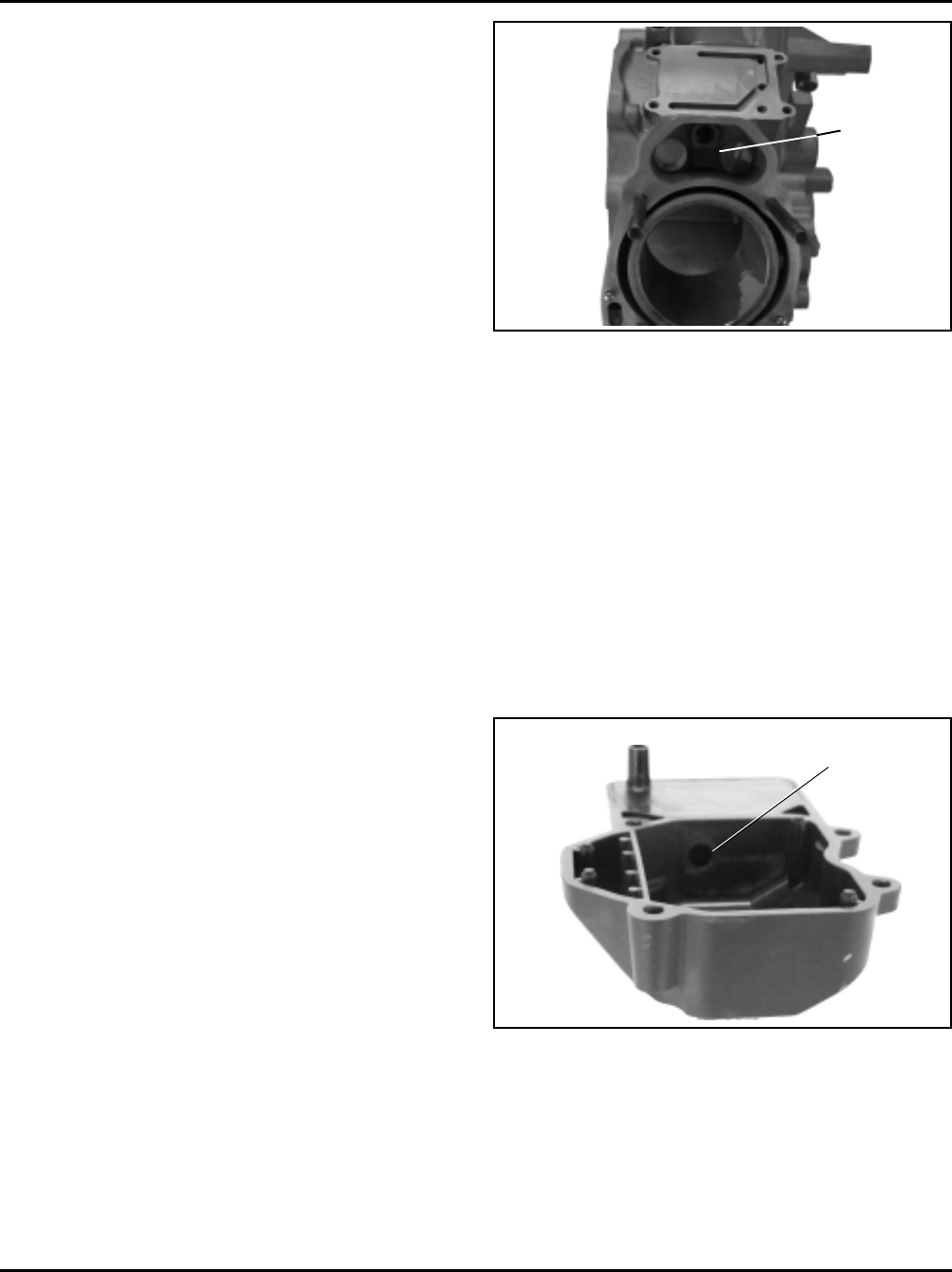
vent the air entering that head cavity. The breather inlet
hole (see Figure 6-7) is positioned so most of the oil
mist has already dropped out before the air enters the
breather. A series of baffles and a screen separate the
remaining oil as the air moves through the inside. A
hose connects the breather outlet to the air cleaner
base. The vented breather air is mixed with the
combustion air, on its way to the combustion chamber.
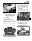
Figure 6-7. Inlet Hole in #1 Valve Cover.
The upward travel of the pistons closes the reeds and
creates a low vacuum in the lower crankcase. The
combination of low pressure above and low vacuum
below forces any accumulated oil out of the #2 head
area into the crankcase. On the #1 side, atmospheric
pressure above and vacuum below, draws any oil
toward the crankcase.
Breather
Reed
Inlet Hole