


11.6
Section 11
Reassembly
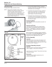
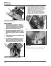
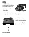
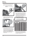
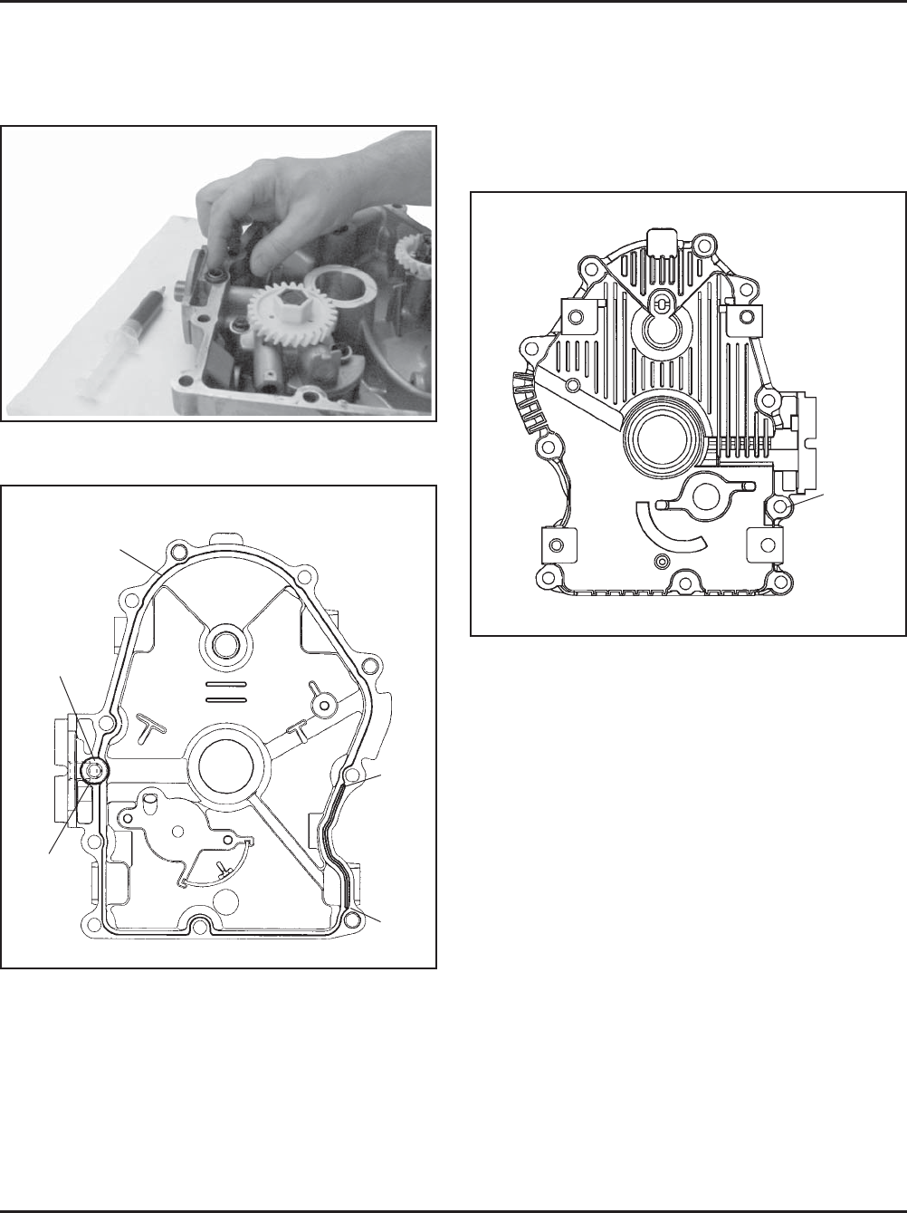
3. Install the O-Ring in groove as shown. See Figure
11-14. Apply a 1.5 mm (1/16 in.) bead of sealant
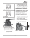
to the sealing surface of the oil pan. See Figure
11-15 for the sealant pattern.
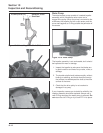
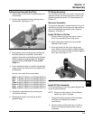
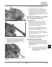
6. Install the ten hex. flange screws securing the oil
pan to the crankcase. Torque fasteners in the
proper sequence to 24.4 N·m (216 in. lb.). See
Figure 11-16 for the proper torque sequence. On
some engines one of the ten mounting screws is
plated. The plated screw should be installed in the
#6 hole shown in Figure 11-16.
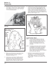
Figure 11-16. Oil Pan Torque Sequence.
Install Cylinder Studs
NOTE: Do not reinstall or attempt to reuse any
cylinder studs that have been removed.
Discard any stud(s) removed. If any of the
cylinder studs were removed from the
crankcase, install new studs at this time
as follows:
NOTE: Two different studs were used in production
and cannot be interchanged or damage to
the threads in the crankcase casting will
occur. Use only the correct replacement
stud(s). Refer to the parts manual for specific
part number when ordering.
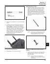
1. Identify the longer threaded end of new stud.
See Figure 11-17. If Dri-Loc Loctite
®
is not
visible, apply Loctite
®
No. 272 to 5-6 threads
approximately 7 threads from the bottom. See
Figure 11-17.
5
3
1
2
4
6
7
8
9
10
Plated
Screw
Location
Figure 11-14. Installing O-Ring in Groove
of Oil Pan.
Figure 11-15. Oil Pan Sealant Pattern.
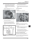
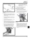
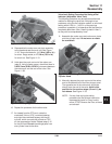
4. Make sure end of governor cross shaft is lying
against the bottom of cylinder 2 inside the
crankcase. See Figure 11-9.
5. Install oil pan to crankcase. Carefully seat the
camshaft with shim and crankshaft into their
mating bearings. Rotate the crankshaft to help
engage oil pump and governor gear meshes.
Point
‘‘B’’
Point
‘‘A’’
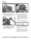
Fill Groove
Between
Points ‘‘A’’
and ‘‘B’’ with
RTV.
Apply 1.5 mm (1/16 in.)
bead of Sealant
RTV Must
Be All
Around
O-Ring
Groove
O-Ring