


5.11
Section 5
Fuel System and Governor
5
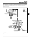
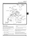
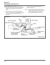
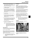
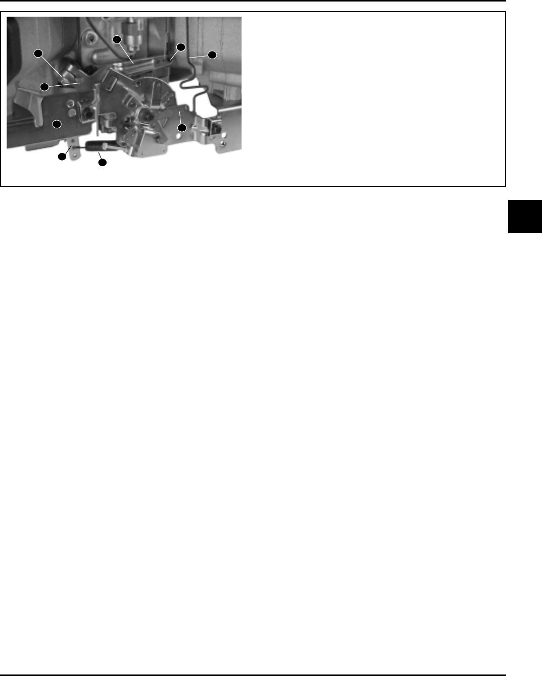
Figure 5-7. Governor Controls and Linkage (External).
Adjustments
General
The governed speed setting is determined by the
position of the throttle control. It can be variable or
constant, depending on the engine application.
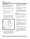
Initial Adjustment
Make this adjustment whenever the governor lever is
loosened or removed from the cross shaft. See
Figure 5-7 and adjust as follows:
1. Make sure the throttle linkage is connected to the
governor lever and the throttle lever on the
carburetor.
2. Loosen the hex. nut holding the governor lever to
the cross shaft.
3. Move the governor lever towards the carburetor
as far as it will move (wide open throttle) and hold
in position.
4. Insert a nail into the hole on the cross shaft and
rotate the shaft counterclockwise as far as it will
turn. Tighten hex. nut to 9.9 N·m (88 in. lb.).
Sensitivity Adjustment
Governor sensitivity is adjusted by repositioning the
governor spring in the holes on the governor lever. If
speed surging occurs with a change in engine load,
the governor is set too sensitive. If a big drop in speed
occurs when normal load is applied, the governor
should be set for greater sensitivity. See Figure 5-7
and adjust as follows:
1. To increase the sensitivity, move the spring closer
to the governor cross shaft.
2. To decrease the sensitivity, move the spring away
from the governor cross shaft.
1. Governor Lever Hex. Nut
2. Governor Cross Shaft
3. Governor Lever
4. Throttle Lever Linkage
5. Choke Linkage
6. Choke Actuating Lever
7. Governor Spring
8. Speed Control Bracket
9. Governor Lever (Holes for Sensitivity
Adjustment)
3
1
2
4
5
6
7
8
9