


11.22
Section 11
Reassembly
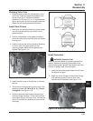
3. Place the small sleeve spacer onto the stud, in
the center of the intake manifold. If the stud was
removed from the manifold, apply Loctite
®
No. 290
to the lower set of threads and install until stud
bottoms, or an exposed height of 32 mm (1.26 in.)
is obtained.
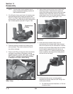
4. Apply rubber lubricant to the inner surfaces of the
disconnected hoses and mating surfaces on the
thermostat housing and water pump.
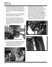
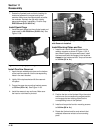
5. Set the radiators and cooling system, with the
hoses attached, down into its general position.
Connect the hoses to the inlet of the water pump,
and the outlet of the thermostat housing. Secure
each connection with the respective hose clamp.
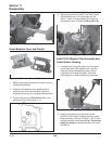
The tangs must be positioned outward. See
Figure 11-74.
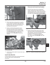
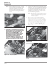
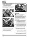
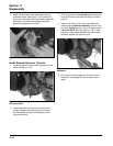
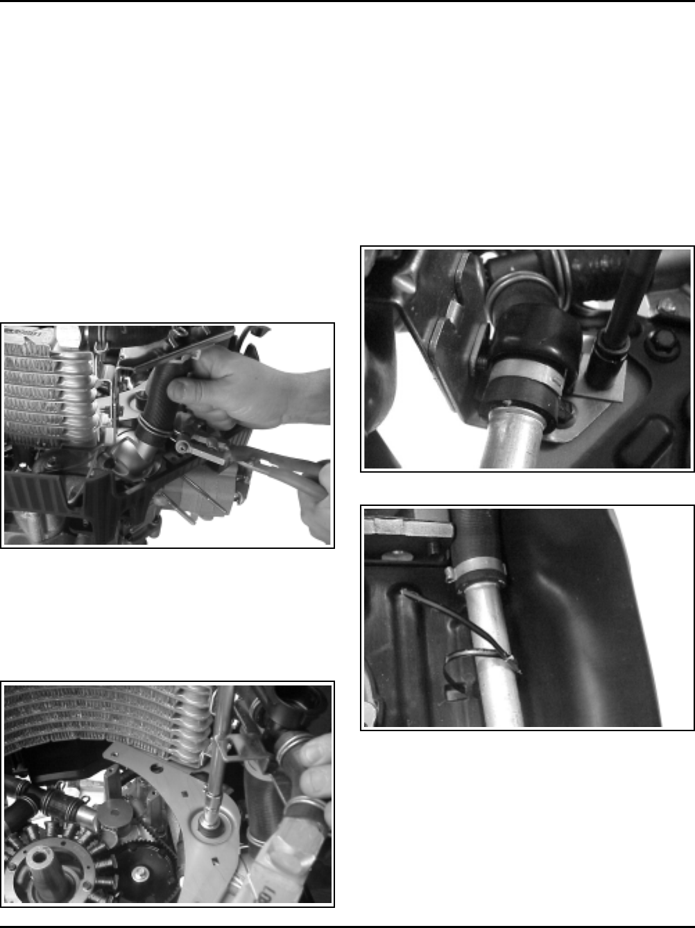
Figure 11-75. Torquing Center Nut.
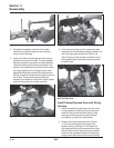
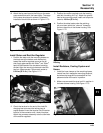
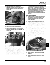
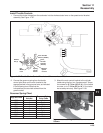
Figure 11-76. Rear Bracket/Clamp.
Figure 11-74. Installing Clamp on Thermostat.
6. Position the rubber mount assembly over the stud
with spacer on the intake manifold. Apply rubber
lubricant to top of mount and install the flat
washer and hex. flange nut. Torque the nut to
9.9 N·m (88 in. lb.). See Figure 11-75.
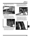
7. Align the rear mounting bracket with the
corresponding set of holes in the crankcase.
Position the half clamp over the hose and install
the two hex. flange screws. See Figure 11-76.
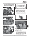
Allow the entire cooling system assembly to
center itself within the constraints of the mounts,
then torque the screws to 10.7 N·m (95 in. lb.)
if a first time/initial installation, or to 7.3 N·m
(65 in. lb.) anytime thereafter. Close, but do not
tighten the metal tie strap around lower tube. See
Figure 11-77. Tightening of tie strap must be
performed after the electric starter assembly
has been installed in the following sequence.
Figure 11-77. Tie Strap.